This page provides information on the command structure and port settings for communicating with the QTFM. This is normally performed automatically by the QuSpin user interface, but the simple communication also allows for full access using a terminal emulator.
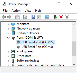
Figure 1: Windows Device Manager showing a list of USB Serial Com Ports devices.
This page last updated on May 16, 2017.
The QTFM electronic control unit (ECU) accepts serial commands from a computer through a USB virtual Com port using the provided Power/Coms board (USB-UART bridge), or by directly accessing the UART Rx and Tx lines from the ECU. A simple terminal emulator (such as Tera Term or minicom) can be used to fully control the mag and stream data. The USB bridge uses the FT232RL chip. If drivers are not loaded automatically through Windows, they can be downloaded here.
Serial port settings:
Baud rate: 115200
Data: 8 bit
Parity: none
Stop: 1 bit
Flow control: none
Terminal new-line:
Receive: CR
Transmit: CR+LF
The digital stream from the sensor electronics is classified into three types, delimited by the first character as described below.
| # | Sensor status and response messages |
| * | State indicator star code indicating state of magnetometer and corresponding to the light sequence on the ECU |
| ! | Magnetometer digital data output. |
The magnetometer data is sent as lines of ASCII text and is delimited by the ‘!’ character with the line terminated by the carriage return and linefeed characters (\r \n). The composition of the data line changes to include more data at slower decimation times. Decimation modes range from 2 to 11. The table below shows the data line format for different decimation modes. The magdata value is converted to nanoTesla by dividing by 6009.342147 (or alternatively multiplying by 1.664075660e-4).
| Dec. mode | Data Format |
| 2 | !magdata\r\n |
| 3 to 5 | !magdata@signalstrength\r\n |
| 6 to 11 | !magdata@signalstrength^cyclecounter\r\n |
The following table provides a list of single-character ASCII commands for operating the QTFM (case sensitive).
| Command | ASCII | Decimal | Comments |
| Auto Start | > | 62 | Initiate the automated sensor startup routines |
| Change Data Rate | o | 111 | Cycles through data decimation time according to T = 6.144e-4 seconds *2^x where x cycles from 2 to 11 |
| Coms check | ! | 33 | Reports back as "#Check" |
| Data Rate Announcement | p | 112 | Query decimation time. Returns time in seconds |
| Serial Number Announcement | q | 113 | Query serial number of the magnetometer |
| Star Code Announcement | r | 114 | Query current star code/magnetometer state |
| Firmware Announcement | s | 115 | Query firmware version loaded on the ECU |
| Manual RF Lock On | B | 66 | Manually activate RF lock |
| Manual RF Lock Off | C | 67 | Manually deactivate RF lock |
| Line Filter On | y | 121 | Apply a line filter at 50 Hz and 60 Hz. Not recommended for taking data |
| Line Filter Off | z | 122 | Remove 50 Hz and 60 Hz line filter |
| ISR On | a | 97 | Restart ISR |
| ISR Off | b | 98 | Disable ISR |
| Zero cycle counter | ^ | 94 | Resets the cycle counter to zero |
| Reset Mag | _ | 95 | Reboot the ECU |
| Commands to change startup conditions: | These should be issued through a terminal program following ISR Off command |
| ~sup0 | Magnetometer starts up in dormant unlocked mode |
| ~sup1 | Magnetometer powers up and begins autolock procedure |
| ~drt'x' | Change default decimation time from startup. 'x' represents a number starting from 2 with decimation time according to T = 6.144e-4 seconds *2^x. |
The following table provides a description of the star codes that represent the current state of the magnetometer, reflected by the LED pattern/color on the ECU. Star codes messages are ASCII strings sent by the ECU over the serial com with the following form: “*” followed by a number from 0 to 5. They are sent upon state change of the magnetometer or can be queried with the single-character command ‘r’.
| Star Code | LED State Indicator | Description |
| *0 | Red flashing | laser off |
| *1 | Red solid | laser on |
| *2 | Green flashing | laser locked, rf unlocked, cell unlocked |
| *3 | Green solid | laser locked, rf locked, cell unlocked |
| *4 | Blue flashing | laser locked, rf unlocked, cell locked |
| *5 | Blue solid | laser locked, rf locked, cell locked |
Once the sensors laser, RF, and cell temperature have locked the analog output can be read from the BNC attached to the ECU. The analog signal and digital signal can both be read simultaneously. The analog signal comes from a 16bit DAC (Digital to Analog Converter) which receives a 1600Hz digital signal that is converted into a voltage ranging from 0 – 4.096V. The analog signal can be centered, and gain adjusted using the commands in the table below. When the analog signal is centered a digital output message will indicate the starting magnetic field, and the analog voltage will start at 2.048V. The voltage change(ΔV) is converted to nanotesla(ΔnT) using the equation “ΔV= ΔnT/2.66252105615*2^g” or “ΔnT = ΔV*(2.66252105615*2^g )” where ‘g’ is the analog gain variable that can be modified with the commands below.
| Command | ASCII | Decimal | Comments |
| Center Analog Signal | @ | 64 | Analog signal is centered at 2.048V |
| Increase Analog Gain | & | 38 | Analog gain variable ‘g’ is decreased by 1 |
| Decrease Analog Gain | % | 37 | Analog gain variable ‘g’ is increased by 1 |
Analog example: As soon as the QTFM sensor is in a fully locked state it will output total magnetic field data (magdata). The first magdata point is assigned as the center point of the 16-bit DAC. If the first data point read is 50,001.0..nT then that is set at 2.048V. If the magnetic field increase above 50,001.0..nT then the DAC will output a voltage higher than 2.048V, and if the magnetic field decreases below 50,001.0..nT the DAC will output a voltage lower than 2.048V. The rate at which the DAC voltage changes with respect to the magnetic field is determined by the Analog gain variable ‘g’, which is initially set a 3. So, if the DAC voltage is increased to 3.048V the magnetic field can be calculated with the equations ΔnT = ΔV/(2.66252105615*2^g ). Where g = 3, ΔV = 1 therefore ΔnT = 1/(2.66252105615*2^3) = 0.04694798552nT. So, the total magnetic field is 50,001.0000nT +0.04694798552nT. The DAC will track the magnetic field until the voltage range is saturated at 0V or 4.096V. To reset the center point of the DAC voltage the Center Analog Signal (CAS) command should be sent. Once the CAS command is sent a new magdata point is captured and assigned to the center point of the DAC at 2.048V. As soon as the CAS command is sent a message will be sent through the digital output to inform the user what total magnetic field is associated with the 2.048V DAC output voltage. To adjust the rate at which the DAC output Voltage changes with respect to the magnetic field use the Increase/Decrease Analog Gain commands to adjust the analog gain variable ‘g’. To widen the magnetic field range that the DAC output voltage covers before hitting saturation the Analog Gain should be decreased. Note the analog gain variable is increased by one when the Decrease Analog gain command is sent. When the Analog gain is adjusted a message verifying the analog gain variable is sent through the digital output. The analog gain variable is an integer value with a range from 1 – 16.