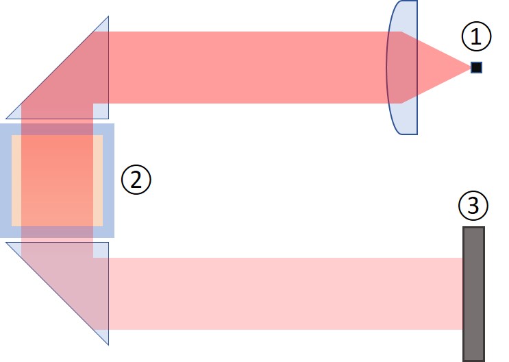
Figure 2: A laser diode 1 produces light that is tuned to the resonance frequency of the alkali atoms. The light beam is collimated and directed to pass through a glass cell 2 containing the vapor of alkali atoms. The transmitted light beam is directed onto a photodiode 3.
The QuSpin Zero-Field Magnetometer (QZFM) is based on zero-field resonance with a single laser beam. The basic configuration of our QZFM is shown in Figure 1. Light from a precisely tuned semiconductor laser (1) passes through a glass vapor cell containing rubidium atoms (2) and is captured by a photodetector (3). When the background magnetic field is equal to zero, the rubidium atoms become largely transparent. A magnetic field in a direction perpendicular to the light path causes the atoms absorb more light. The photodetector senses this change in transparency and produces an electric current proportional to the light transmitted through the vapor cell. In this way, a magnetic signal is converted to an electric signal forming a zero-field magnetometer.
To introduce the concept of a zero-field (ZF) resonance [Dupont Roc, 1969], imagine that the magnetometer is in an absolute zero magnetic field environment. If a magnetic field is applied in a direction perpendicular to the light beam and the amplitude of the applied field is swept from a positive to a negative value, the transparency of the rubidium atoms changes such that maximum transparency is observed when the atoms experience a magnetic field that is very close to zero. If you look at the output of the photodetector as a function of the applied field, you will see that the output has a Lorentzian line shape. This Lorentzian output is referred to as the ZF resonance (see Fig. 2) and is the response of the magnetometer. Its typical width (full width at half max – FWHM) is around 30 nT in our QZFM.
The field value is given by the deviation from the peak of the Lorentzian. A simple way to measure this deviation is by looking at the derivative of the Lorentzian which can be obtained through lock-in detection. We apply a small oscillating magnetic field at about 1 kHz (called a modulation field) using an internal coil. With a phase-sensitive lock-in amplifier referenced to the modulation frequency, we demodulate the photodetector output to produce an anti-symmetric line shape called a dispersion curve (See Fig. 2). The dispersion curve has a maximum slope at zero field and functions as the output of the magnetometer.
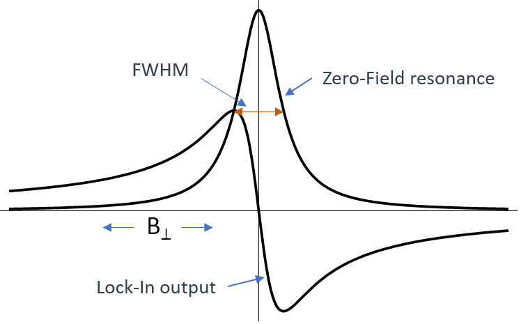
Figure 2: The Zero-Field (ZF) resonance is the output of the photodetector as the magnetic field is scanned from a positive to a negative value in the direction perpendicular to the light beam through the vapor cell. The FWHM of the ZF-resonance is typically 30 nT. The demodulated output of the lock-in amplifier (also referred to as the error signal) gives an asymmetric Lorenztian shape.
The sensitive axis of the magnetometer is defined by the direction of the modulation field (projected on a plane perpendicular to the light beam). To make the magnetometer simultaneously sensitive to two orthogonal axes (perpendicular to the light beam), we apply two separate modulation fields using separate orthogonal coils.
In a multi-channel system in which several OPMs are placed close to one another, we modulate all the sensors with a common drive signal to avoid interference from adjacent sensors. An electronics module designated as the ‘Master’ generates the modulation signal and distributes it to all other electronics modules designated as the ‘Slaves’. While operating sensors with the same modulation drive signal resolves aliasing type effects, one problem that remains is that the superposition of the modulation fields from adjacent sensors can slightly change the effective direction of the net modulation field experienced by the vapor cell, thereby changing the direction of the sensitive axis of the magnetometer. We have developed solutions to mitigate this so called ‘cross-talk’ effect that we are implementing in our large scale multi-channel systems.
ZF-OPMs are extremely sensitive and because they require zero field environment for operation, a magnetically shielded environment is needed to run these sensors. Magnetically shielded rooms (MSR) are not perfect and generally have some residual fields inside (several tens of nT). These residual fields typically require the user to outfit the MSR with large coils that can globally offset and zero the background field. This is not always practical. Instead, we have integrated a set of three axis orthogonal magnetic coils in the sensor head that can locally zero the field around the vapor cell of each OPM. The field zeroing coils can compensate up to 50 nT residual fields and the process is fully automated, requiring just a few seconds. When multiple sensors are operating in close proximity, the field zeroing process is run simultaneously for all sensors which causes the combined magnetic field from all sensors to collapse in a way where each sensor experiences zero field to the greatest extent possible. The field zeroing process should be repeated each time the background field experienced by the OPM changes significantly or when the sensor arrangement changes.
The bandwidth of our ZF-OPM is around 150 Hz and is limited by the physics of the system. The frequency response of the OPM behaves like a first-order low-pass filter with roll-off at 150 Hz. In addition, we have a sixth-order hardware digital filter at 500 Hz which eliminates any residual response above this frequency. Any possible increase in the bandwidth will come at the cost of sensitivity. The uncompensated linearity of the magnetometer response (amplitude of the output voltage as a function of the amplitude of the applied field) is governed by the non-linearity of the error signal around zero field (for example 1 nT field amplitude can cause a 1% deviation from linearity).
For optimal sensor performance, the vapor cell is heated to approximately 150° C to increase the vapor density. This causes a slight warming of the sensor housing near the cell.
References:
Dupont-Roc, J., Haroche, S. & Cohen-Tannoudji, C., Detection of very weak magnetic fields (10-9 gauss) by Rb zero-field level crossing resonances, Phys. Lett. A 28, 638–639 (1969).