QTFM Gen-2 is a pulsed, rubidium optically pumped magnetometer (OPM) based on an optical detection scheme called Free Induction Decay (FID). The underlying physics and operation is described below.
Optical schematic
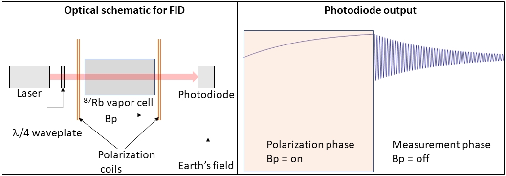
The figure above (left) shows the optical schematic of the magnetometer sensor head. First, light from a 795 nm VCSEL laser is circularly polarized using a quarter waveplate. Next, the circularly polarized light passes through a transparent rubidium vapor cell. After passing through the vapor cell, the light is captured by a photodetector. The vapor cell is electrically heated to roughly 80 deg. C to increase the rubidium vapor pressure and the laser wavelength is electronically locked to the rubidium D1 optical transition.
Pulsed operation
The sensor operation is divided into two phases that repeat every 1ms (cycle time). For the first 500us, a strong polarizing magnetic field (Bp) parallel to the light beam is turned on using a set of Helmholtz coils enveloping the vapor cell. The combination of the light beam and the longitudinal polarizing field causes the rubidium atoms to become spin-polarized (aligned with the polarization field). Next, the polarizing field is rapidly turned off in less than 1us. Once the polarization field is turned off, the measurement phase begins.
The measurement phase
Rapidly switching off of the polarization field causes the rubidium atoms to precess (oscillate) about the earth’s magnetic field. The rubidium precession frequency is directly proportional to the background magnetic field. The precessing rubidium atoms modulate the light passing through the vapor cell which enables real-time observation of this precession, for example using the amplified photodiode output plugged into an oscilloscope [Figure (right)]. In QTFM Gen-2 (M), the precession lasts for about 500us and constitutes the measurement phase of the cycle.
From frequency to field
During the measurement phase, the raw electrical output from the photodiode is amplified and sent to a built-in high-performance frequency counter. The frequency counter measures the rubidium precession frequency and infers the accurate value of the background magnetic field— thanks to the fixed relationship between background magnetic field and precession frequency given by 6.998 Hz/nT. As an example, if the precession frequency is found to be 350 kHz, the background field is determined to be 50014.289 nT. In each 1ms cycle, one magnetic field measurement is made.
Why it is a total-field magnetometer
The precession frequency depends only on the magnitude of the background magnetic field [√(Bx2 + By2 + Bz2), and not on the individual field vector components of the field (Bx, By, Bz). For this reason, the QTFM-Gen 2(M) is a scalar or “total-field” magnetometer, and not a vector magnetometer like QZFM or a fluxgate.