Scalar Total-Field Atomic Magnetometer

QTFM Gen‑2

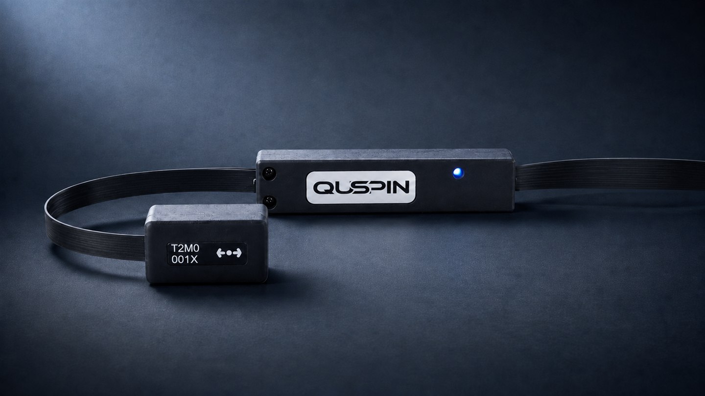
The QuSpin Total-Field Magnetometer (QTFM) is a compact, high-sensitivity atomic magnetometer combining scalar total-field and three-axis vector measurements. Its accuracy, stability, low power, and small form factor make it ideal for applications ranging from magnetic observatories to mobile platforms such as UAVs.
Overview

Precision total-field measurement in a compact instrument

Scalar atomic magnetometers have been used in geophysical surveying for decades, but high-performance instruments were traditionally large, power-intensive, and difficult to deploy on small platforms.

The QTFM Gen‑2 combines very high scalar sensitivity with high bandwidth and a small dead zone, while substantially reducing size, weight, and power consumption.

The compact sensor head and electronics can be integrated into walking systems, vehicles, small unmanned aircraft, fixed stations, and custom research instruments—bringing high-performance total-field measurements to platforms that could not support previous generations of atomic magnetometers.

Scalar sensitivity <5 pT/√Hz typ. 3
Measurement bandwidth 500 Hz
Dead zone <±7° axial cone
Sensor and electronics 41 g
Total operating power 2.5 W
Specifications

Technical specifications

Specifications may vary by sensor version, firmware, vector option, and supplied interface hardware. Confirm requirements for specialized integrations with QuSpin.

Measurement performance

Magnetometer type Pulsed rubidium total-field
Measurement method Free induction decay
Scalar sensitivity <5 pT/√Hz (typ. 3 pT/√Hz)
Derived-vector sensitivity <0.1 nT/√Hz, optional
Output data rate Scalar ≤1000 Hz · triaxial ≤250 Hz
Bandwidth Up to 500 Hz
Operating range 1,000–150,000 nT typ.
Heading error <3 nT, uncompensated
Dead zone guide Axial cone, <±7° (typ. <5°)
Slew rate limit None
Maximum field gradient Approximately 300 nT/cm
Operating temperature −15 to +55 °C

Physical

Sensor head 17.7 × 19.8 × 35.8 mm
Electronics Control Unit 14.7 × 24.4 × 92.3 mm
Weight 12 g sensor head + 29 g ECU (6.5 g without housing)

Electrical and communication

Input power +5 V via Standard Comms Board, or 10–12 V
Operating power Approximately 2.5 W
Startup power Approximately 3.5 W
Digital communication UART; USB via Standard Comms Board
Filtering Programmable onboard digital filtering
Calibration None required

Release notes  ·  Gen‑1 archive

Capabilities

Features

Derived three-axis vector outputs

Optional add-on providing integrated, stable, low-noise vector outputs, synthetically derived from the scalar measurement.1

Flat spectral response

No frequency-dependent response roll-off across the measurement band.

Customizable digital filters

Built-in low-pass, high-pass, and notch filters, configurable in firmware.

Precise multisensor synchronization

Multiple sensors synchronize precisely for gradiometer configurations.

Negligible dead zones

A single small axial dead zone, the smallest of its kind in the industry.

No slew rate limitations

Tolerates extremely magnetically noisy environments without losing lock.

High-resolution frequency counter

Built-in counter for precision determination of the precession frequency.

1 Vector outputs are synthetically derived from scalar measurements by applying bias fields in interleaved measurement cycles.

Vector mode operation
Measured data

Typical performance

The intrinsic sensitivity of a magnetometer is only one factor in field performance. Measurements from drones, vehicles, and walking platforms can also include environmental noise, platform-generated magnetic fields, motion effects, heading error, and positioning uncertainty. The figures below show representative sensor performance under controlled conditions.

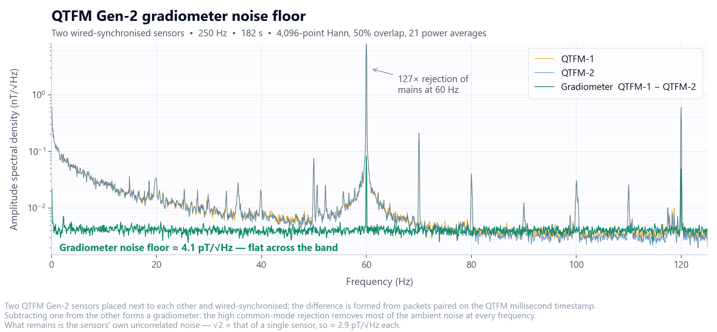
Gradiometer noise floor

Amplitude spectral density from 0 to 125 Hz for two wired-synchronised QTFM Gen-2 sensors, labelled QTFM-1 and QTFM-2, and their difference. The two individual sensor traces overlap almost exactly and are dominated by ambient noise, rising to about 0.2 nT per root hertz at low frequency with sharp peaks at 50, 60, 70, 80 and 120 Hz. The gradiometer trace formed by subtracting one sensor from the other is flat at about 4.1 pT per root hertz across the whole band, roughly 127 times below the sensor traces at the 60 Hz mains peak.
Two synchronised sensors side by side. Subtracting one rejects the common ambient field, leaving a flat 4.1 pT/√Hz floor — √2 × a single sensor, so ~3 pT/√Hz each. More on gradiometer mode →

Long-term stability

Long-term drift measurement to be added
Representative drift over an extended run under stable conditions, showing the behaviour that matters for surveys lasting hours rather than minutes.
Package

What is included

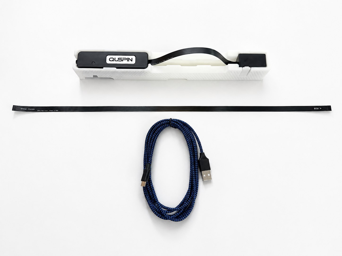
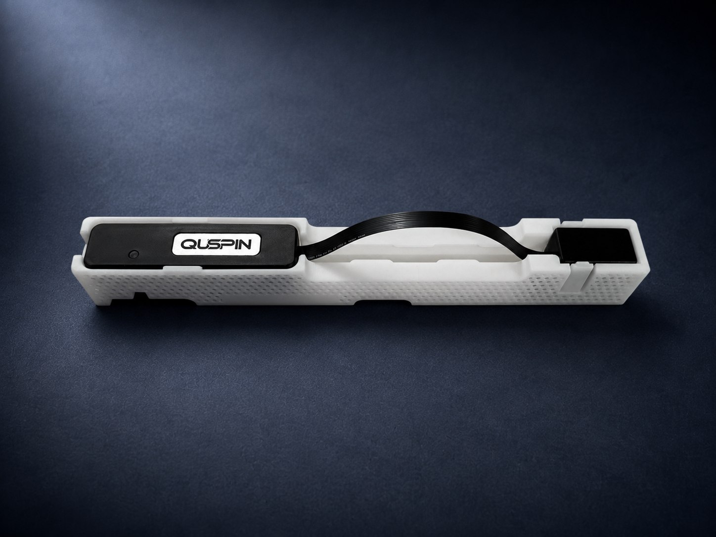
Each standalone QTFM Gen‑2 is supplied as a sensor and electronics package suitable for laboratory evaluation and integration into a larger measurement system.

The standalone QTFM Gen-2 package on a white background: the sensor head and Electronics Control Unit in their carrier, the flat power and comms flex cable, and the braided USB interface cable. The Standard Comms Board is under the ECU and is not visible.
QTFM Gen‑2 sensor head
Electronics Control Unit (ECU)
Standard Comms Board — not visible, mounted under the ECU
USB interface cable
QTFM control and configuration software
Access to the user guide and firmware resources

The Standard Comms Board provides USB communication and power connectivity for setup and laboratory operation.

Vector attachment, Advanced Comms Board, rugged packaging, GPS, and battery hardware are separate options.

Use cases

Representative applications

The QTFM enables precise magnetic measurements for airborne, mobile, and fixed installations.

Magnetic anomaly detection

Detection of submarines, unexploded ordnance, buried infrastructure, archaeological features, and other magnetic targets.

UAV magnetic surveys

High-resolution magnetic surveying from compact, weight-constrained unmanned aircraft.

Geophysics and mineral exploration

Mapping geological structures, mineralization, and subsurface magnetic contrasts.

Power-line monitoring

Measurement and mapping of magnetic fields around transmission and distribution lines.

Magnetic mapping and navigation

Collection of scalar magnetic maps for localization, navigation, and field research.

Reference and platform monitoring

Base-station measurements, observatory monitoring, and characterization of magnetic fields generated by vehicles and electronics.

Sensor or system

Choose the appropriate level of integration

Standalone QTFM Gen‑2

The sensor, ECU, communication interface, and programmable measurement platform needed for laboratory use and custom system integration.

Best suited for

OEM and system integrationCustom research platformsMultisensor and gradiometer developmentUsers supplying their own logger, power, GPS, enclosure, and communicationsFixed or specialized installations

Magpie

Magpie combines the QTFM with the hardware required for a compact field instrument: positioning, timing, data logging, inertial sensing, onboard storage, wireless communication, and portable power support.

Best suited for

Rapid field deploymentWalking surveysUAV integrationBase-station measurementsUsers who prefer an integrated survey instrument
Ecosystem

Options and accessories

Pricing

Pricing

Qty 1–3 $10,000
Qty 4–7 $8,500
Qty 8+ $8,000

Per sensor, US dollars.

Resources

Documentation and resources

Additional QTFM documentation from the previous site — quick reference, configuration, zero-crossing setup, vector-coil calibration, IMU data, serial data format, synchronization, firmware update, and reoptimization — is being migrated and will be grouped here.