Sensor Configuration Options2 [retained in internal flash memory]
| Data Rate | 1/2/4/8/16/32/64/128/1000/2000 ms |
| Print Items | Sensitivity/Data drop counter/Timestamp |
| Filters | 50 or 60 Hz notch/10 Hz low or highpass/20 Hz low or highpass/custom low or highpass/Off |
| Magnetic Environment Scalar | Noisy/Average/Quiet/Auto-optimize/Custom (SZC) |
| Magnetic Environment Vector | Noisy/Average/Quiet/Auto-optimize/Custom (VZC) |
| Vector Mode | Enabled/Disabled (requires add-on vector coils) |
| Automatic Start-Up | Enabled/Disabled |
| Baudrate | 115200/230400/19200bits |
| Sync mode | Master/Slave |
Data Rate: The sensor internally samples the magnetic field at a fixed rate of one measurement/ms. Based on the selected data rate, adjacent measurements are averaged before streaming. For example, at data rate = 4 ms, four adjacent measurements are averaged, and the averaged value is streamed by the magnetometer. The data rate = 1ms can only be when the sensor is configured to 230,400bits/s baud rate.
Vector Data rate: When Vector mode is turned on the scalar data rate is automatically slowed down to half as fast. The data rate for each vector direction is always 1/3 the data rate of the scalar output.
Magnetic Environment settings
The Magnetic environment setting controls how much of the signal is used to calculate each data point. In a good magnetic environment, more of the signal can be utilized to collect better data. In a poor magnetic environment, less of the signal is valid and shouldn’t be used. Magnetic gradient, noise, and dead zone are all factors in the quality of the magnetic environment.
The amount of signal that is used is an arbitrary number that we call scaler ZC(Zero Crossings). The greater the ZC value means that more of the signal is being used. The higher the ZC value means that the sensor is more sensitive, but if the ZC value is too large for the environment the data collected can become invalid. Invalid data will always be marked by the * validation character. The LED on the ECU will flash red for invalid data.
The sensitivity indicator can be used to determine if the right magnetic environment setting is selected. The ASCII command ‘j’ can be used to cycle through the different environment settings.
Fixed Noisy environment, setting 40ZC: The Noisy fixed environment setting is a good option if the sensor is being used in an environment with large magnetic gradients or a lot of magnetic noise. This setting only takes a small portion of the signal that is the strongest. The advantage of this is that it is the least susceptible to collecting invalid data. The disadvantage to this setting is that it is not collecting as much data so the noise floor in this setting is higher.
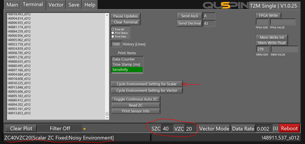
*Note the SZC box indicates what the scalar zero crossings are set to. The VZC is the vector zero crossings. The vector zero crossings are only active if the sensor is in vector mode, otherwise, the VZC box should be ignored. See the Vector webpage for more information on environment settings for the vector feature.
Fixed Quite Environment setting, 200ZC(Recommended): The quiet environment setting is excellent for clean magnetic environments. This setting will be the most sensitive of the fixed environment settings. The disadvantage of this setting is that it is susceptible to collecting invalid data when the magnetic environment is poor.
Fixed Average Environment setting, 100ZC: The average environment setting offers a fixed ZC option that is more sensitive than the Noisy environment setting and less susceptible to collecting invalid data than the quiet environment setting.
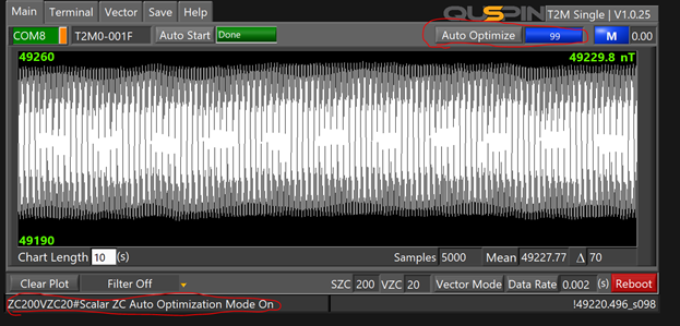
Auto-optimized Mode (Recommended for non-moblie platforms only): The auto-optimized setting will use the sensitivity indicator to automatically set how much of the signal is used (ZC). This is a great option because it will automatically set the ZC to the ideal point where the sensor is the most sensitive. When the sensor is set to this mode it will optimize the zero crossings once the locking process has been completed. The process to optimize the ZC takes about 5seconds, some data points will be invalid during this process. In the auto-optimize mode, the sensitivity indicator is monitored internally so if the data becomes invalid the sensor will automatically re-optimize the ZC. The reverse is true if the signal improves the sensor will automatically re-optimize the ZC to increase the sensitivity. The auto-optimize process can also be initiated by the user with the blank command or the auto-optimize button in the interface. The disadvantage of this mode is that some mag-data points will be invalid during the optimizing process. If the magnetic environment is consistent then the auto-optimization process should only happen once.
Vector Magnetic environment settings: The Vector environment settings work the same way that the scalar environment settings do. There are three different fixed environment modes: Noisy, average, quiet. There is also an automatic optimization option. The Vector and scalar environment settings are independent of each other. If both vector and scalar settings are set to automatic optimization mode the optimal ZC value for the scalar will be selected SZC, and the optimal ZC value for the vector VZC will be selected. If the vector environment setting is set to a fixed mode the VZC will remain at 100 ZC regardless of what the scalar environment setting is set at.
Automatic start-up: When the automatic start-up option is enabled the sensor will automatically initiate its locking process as soon as it receives power. The locking process takes about 30-90seconds. Once the locking process is completed the sensor will start outputting magnetic field data. If the Automatic start-up option is disabled, the sensor will not go into its locking process until it receives the AutoStart command. The automatic start-up can be toggled on and off with the ASCII command ‘O’ (decimal 79).
Baud Rate: The baud rate of the sensor can be changed. It is important to note that once the baud rate is changed the sensor will no longer be able to accept commands in the former baud rate. The sensor must be reconnected to an interface with the appropriate baud rate to communicate with the sensor again. The “(“ command followed by the baud rate you want to set the sensor to will change the baud rate. 115200 bits/s >230400 bits/s >19200 bits/s >115200 bits/s. Each time the baud rate cycle command is sent, the sensor will need to be reconnected to the appropriate baud rate. Tera term is an excellent platform to use to change the baud rate. In faster baud rates you can print more data without running into #POF print overflow errors.
Sync mode: The master and slave configurations are used when syncing multiple sensors. When using a single sensor or using the sensor independent of one another the sensor must be in master mode. Command 32(SPACE) will configure the sensor in master mode. When syncing two or more sensors together sensors can be configured to slave mode with command 33(!). In slave mode, the sensor will not function unless it receives a 1kHz square wave (0-+3.3V) on the sync_in input pin. See the sync sensors section for more information.