Description
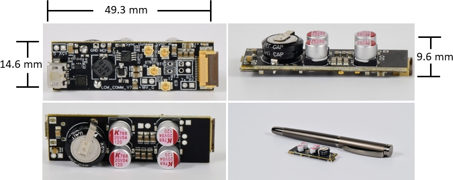
Every QTFM Gen-2 sensor comes with a standard comms board (SCB). The SCB is a bridge to connect the QTFM Gen-2 to a PC using a USB port. We recommend the user test the sensor with the SCB before field deployment. On the standard comms board,
- a USB-UART bridge transmits raw UART signals from the sensor electronics (ECU) to a PC over a virtual COM port
- an onboard switching regulator upconverts +5V from USB to +10V required by the ECU
- supercapacitors clean up and stabilize the USB voltage
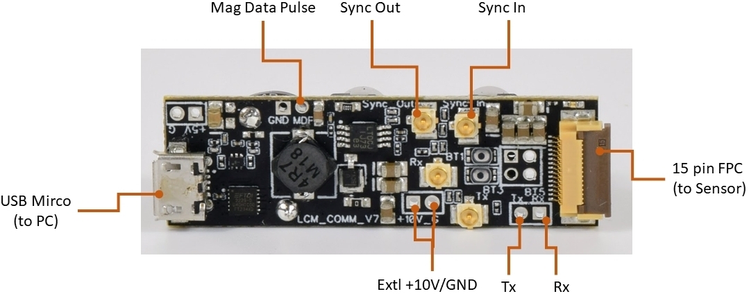
- access to sync in/out, mag data pulse (MDP), and raw UART
Electronic schematic
Connecting the SCB
Connect the sensor
Connect the flex cable from the sensor electronics (ECU) to the 15-pin FPC connector on the SCB.
Connect the PC
Plug a USB type-A to micro-B cable into the SCB and the other end into the PC. The SCB’s UART bridge creates a virtual COM port, which appears in Device Manager.
Connector reference
| Connector | Direction | Signal |
|---|---|---|
| 15-pin FPC | Input | Flex cable from the sensor electronics (ECU). |
| USB micro-B | Both | Power in and data out. Creates the virtual COM port on the PC. |
| Sync out (UMCC) | Output | 1 kHz, 3.3 V square wave. The falling edge marks the start of a magnetic field measurement. Feed it into the sync in of another sensor to lock the two together. |
| Sync in (UMCC) | Input | Accepts a 1 kHz, 3.3 V square wave to synchronize two or more QTFM Gen-2 sensors. |
| Mag Data Pulse (MDP) | Output | 3.3 V pulse, one per printed data sample. Its rising edge gives a jitter-free timestamp for magnetometer data. MDP stays low until the sensor finishes AutoStart, so it doubles as a ready signal. |
| Ext +10 V / GND | Input | Power the sensor from an external +10 V supply instead of the onboard regulator. Requires removing R48 — see below. |
Sync out and sync in are how sensor arrays are built for gradiometry. The full procedure, including master/slave setup and the settings each sensor needs, is in the sync guide.
No COM port appears? The bridge needs FTDI’s VCP driver. The QTFM Gen‑2 user interface installer includes it; if you are not installing the UI, get the driver from FTDI, then unplug and reconnect the board. If a port appears but data is garbled, the baud rate is wrong rather than the driver — see sensor configuration.
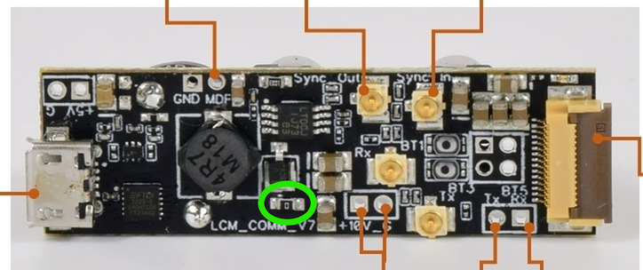
Powering from an external supply
The sensor can be powered from an external +10 V supply through the Ext +10 V / GND pins instead of the onboard +5 V to +10 V switching regulator. Remove R48, circled in green below, before doing so.
Price
Included with every sensor.