Troubleshooting Common Issues:
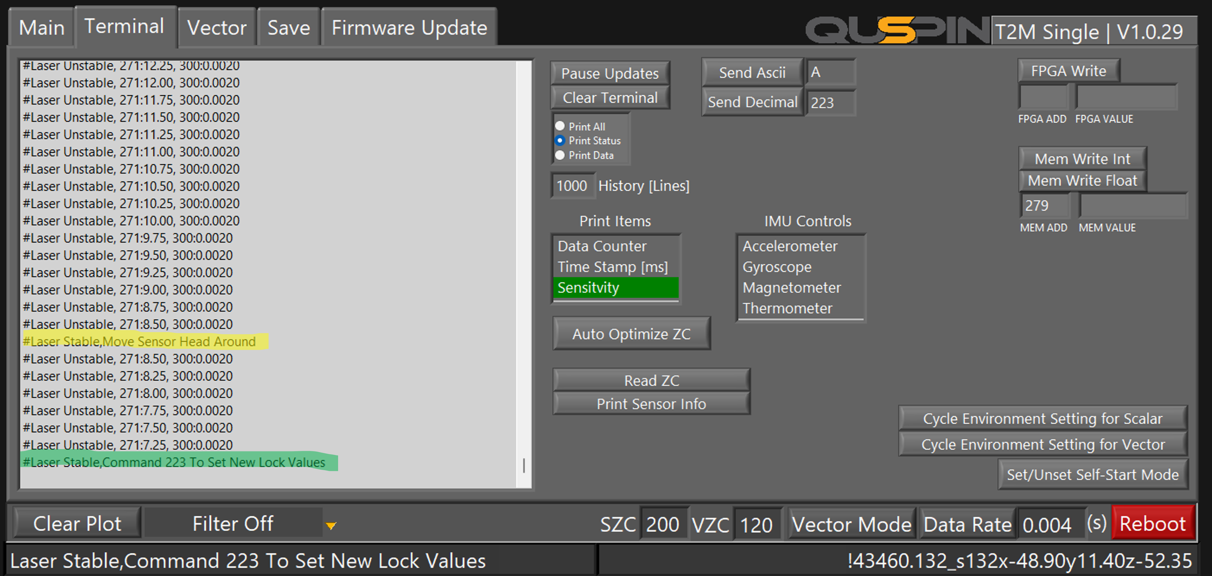
If the sensor is not completing Auto Start, or if the sensor repeatedly enters a state of “#Laser Overheated” and reboots, or if it continuously outputs “#Laser Unstable,” it indicates a need for reoptimization. The steps provided in this guide are designed to address these issues effectively. By following the outlined procedures for reoptimization, you can resolve these operational concerns and restore the sensor to optimal functioning.
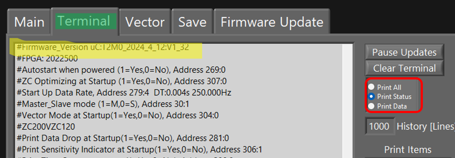
This manual provides detailed, step-by-step instructions tailored for advanced users on troubleshooting and reoptimizing a Gen-2 QTFM sensor using the automated optimization procedures embedded in the sensor’s firmware. Ensure your device’s firmware is version V1_32 or later before beginning. If the firmware version is not V1_32 or later, you can update the firmware using the interface or by following the provided instructions here.
This guide outlines two semi-automated procedures:
- Section 1: For basic settings re-optimization.
- Section 2: For setting laser stabilization parameters.
Preparation:
- Access the User Interface:
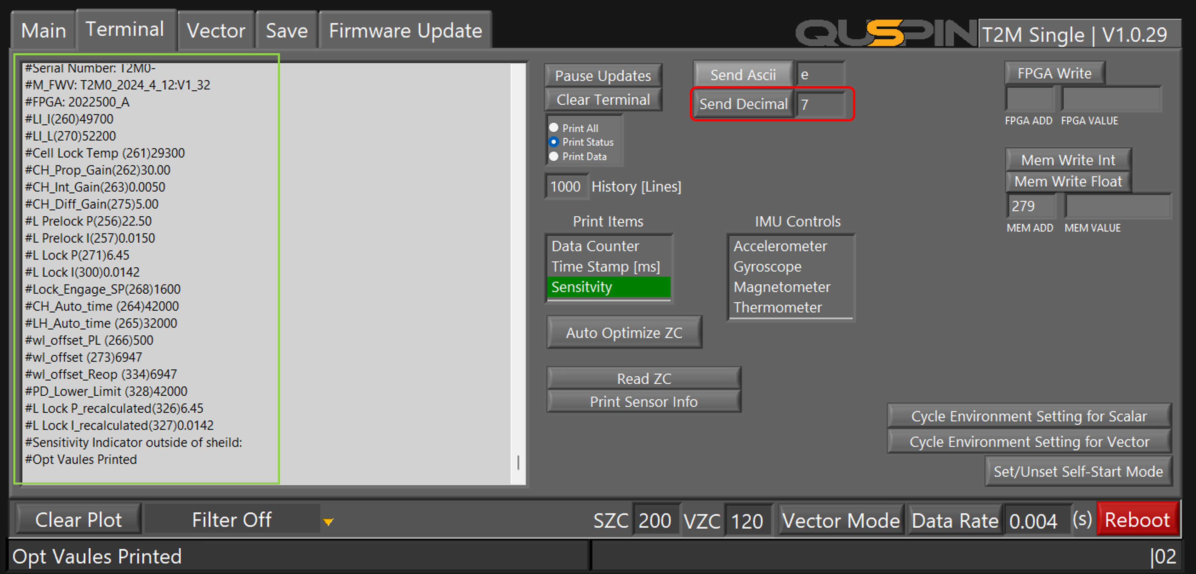
- Print Current Optimization Parameters:
EX. #Mem Address Name (Mem Address) Mem Value.Decimal
#M_FWV: T2M0_2024_1_11:V1_31
#FPGA: 2022500_A
#LI_I(260)50000
#LI_L(270)58500
#Cell Lock Temp (261)35000
#CH_Prop_Gain(262)30.00
#CH_Int_Gain(263)0.0050
#CH_Diff_Gain(275)5.00
#L Prelock P(256)22.50
#L Prelock I(257)0.0150
#L Lock P(271)2.67
#L Lock I(300)0.0059
#Lock_Engage_SP(268)1600
#CH_Auto_time (264)40000
#LH_Auto_time (265)32000
#wl_offset (273)1000
#wl_offset_Reop (334)4321
#PD_Lower_Limit (328)42000
#L Lock P_recalculated(326)2.67
#L Lock I_recalculated(327)0.01
#Sensitivity Indicator outside of sheild:100
#Opt Vaules Printed
-
- The memory address(mem add) is the number inside the parameters, and the number following it is the memory value (mem value). Memory addresses without decimals indicate integers (mem int), and those with decimals indicate floats (mem float).
- None of these parameters should be set to 0 or -1, as these values suggest that the memory address value was overwritten and needs to be set.
- Specifically make sure memory addresses 262 (CH_Prop_Gain) and 263 (CH_Int_Gain) are not set to 0.00, indicating an error. These values do not get reset during the automated optimization processes
- If the values are set to 0.00, use the ‘Mem Write Float’ button to reset:Set memory address 262 to 30.00 and memory address 263 to 0.005.
Section 1: Basic Settings Reoptimization
- Initiate Auto Reoptimization Procedure One:
-
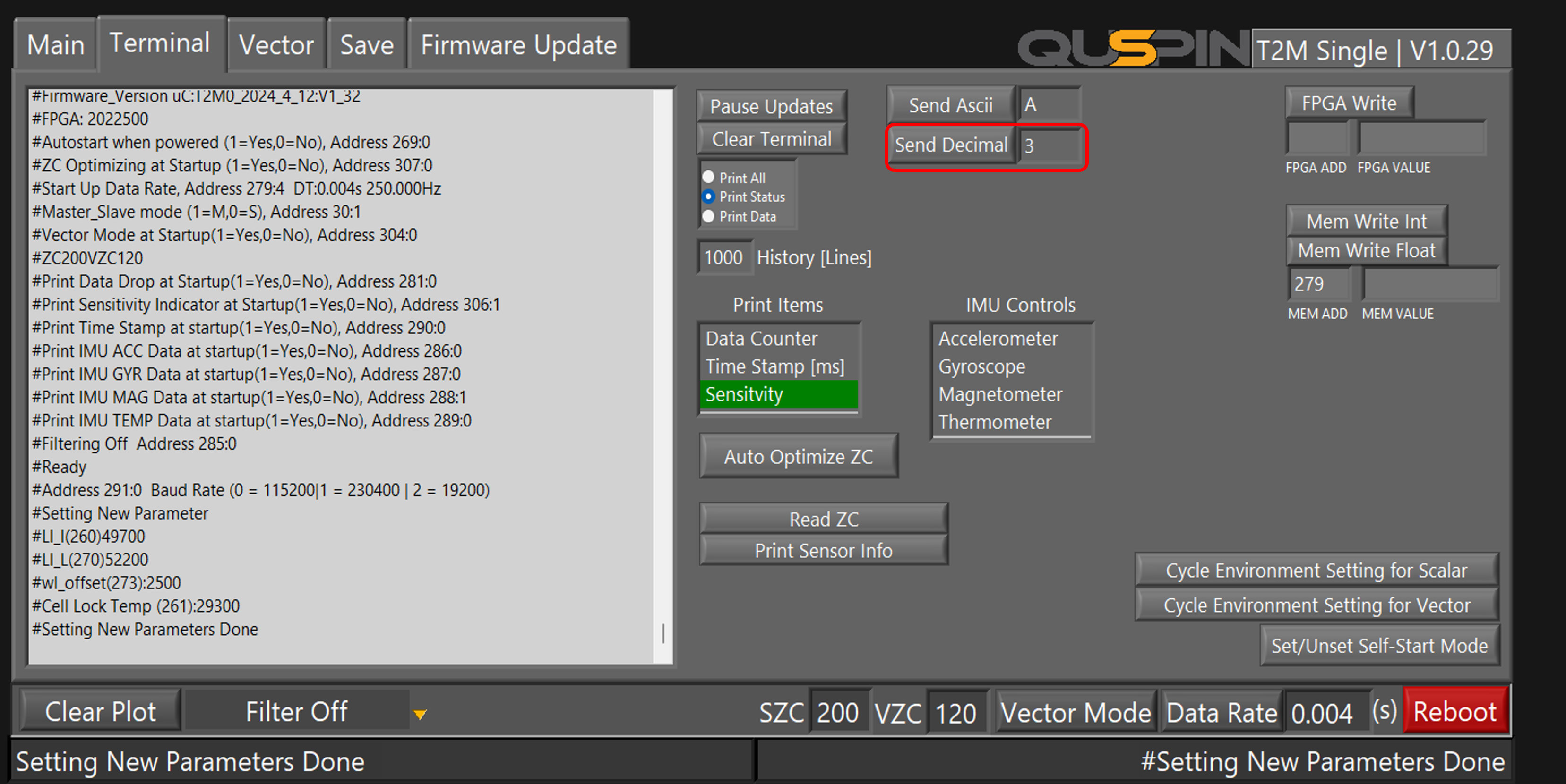
- Enter ‘3’ in the window next to the ‘Send Decimal’ button, then press ‘Send Decimal’ to send the command to the sensor. This initiates the first auto-optimization procedure.
- This process takes about 30 seconds, during which the sensor’s LED turns purple, and the sensor will reboot twice automatically, entering autostart mode.
- Ensure Cell Lock:
-
- Allow the sensor to complete autostart and wait for the cell to lock, as indicated by the stabilization of readings on your display.
- Initiate Further Reoptimization:
-
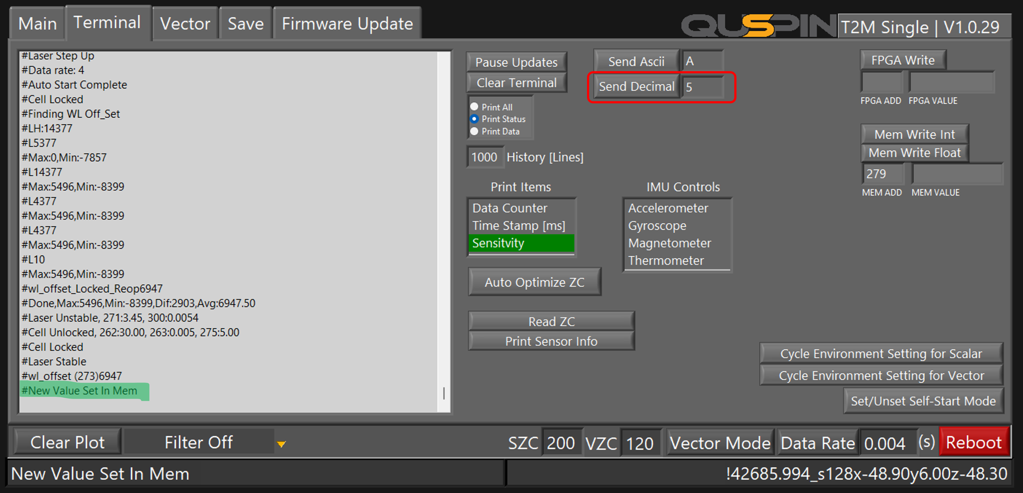
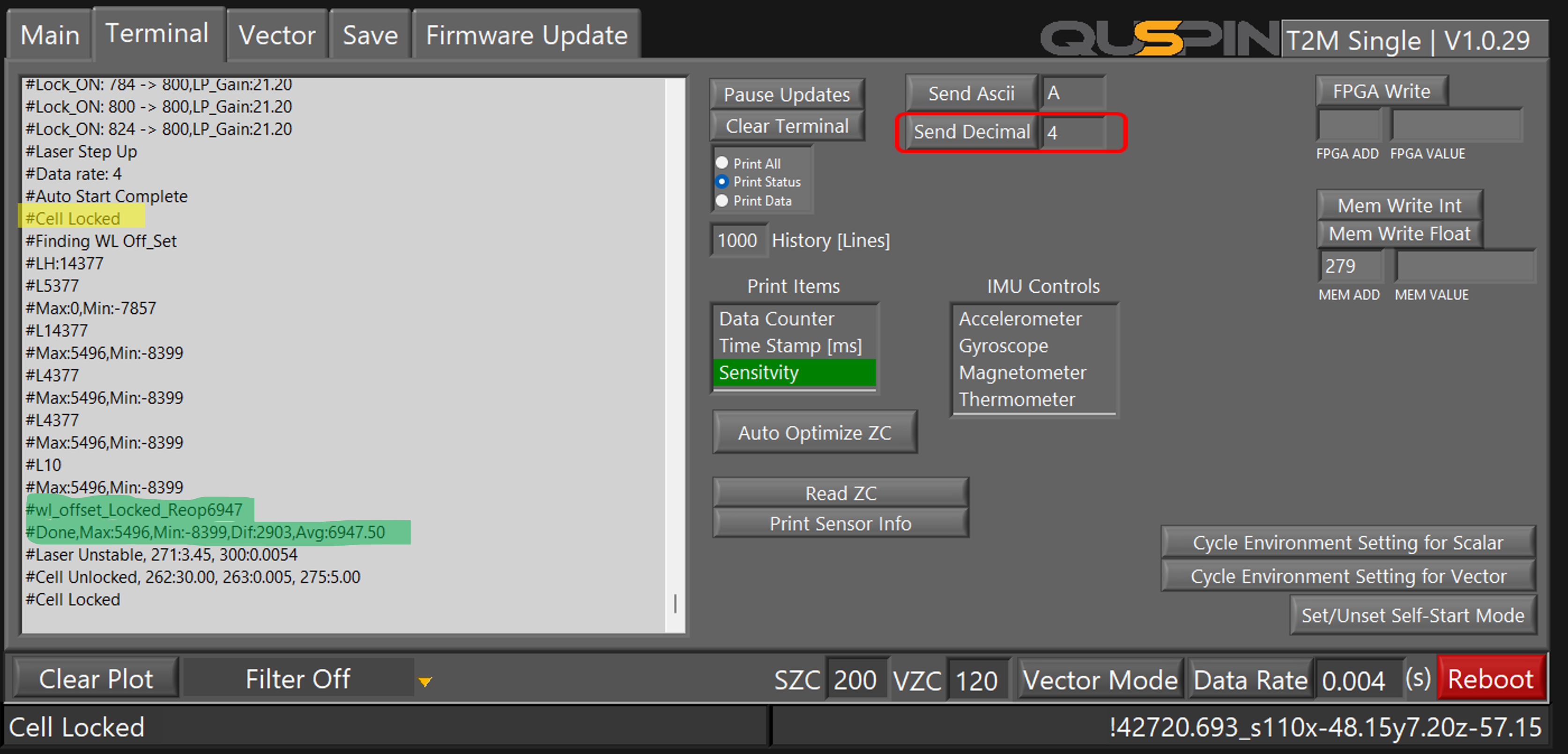
- Once the cell is locked, enter ‘4’ next to the ‘Send Decimal’ button and press it to start the second automation phase.
- This process also lasts about 30 seconds, with the LED remaining purple. Once completed, the sensor attempts to recapture the laser lock and may reboot, which is expected and should not cause concern.
- Save Optimization Settings:
Section 2: Laser Gains Reoptimization
- Verify Sensor Stability:
- Adjust Sensor Position:
- Finalize Laser Reoptimization:
-
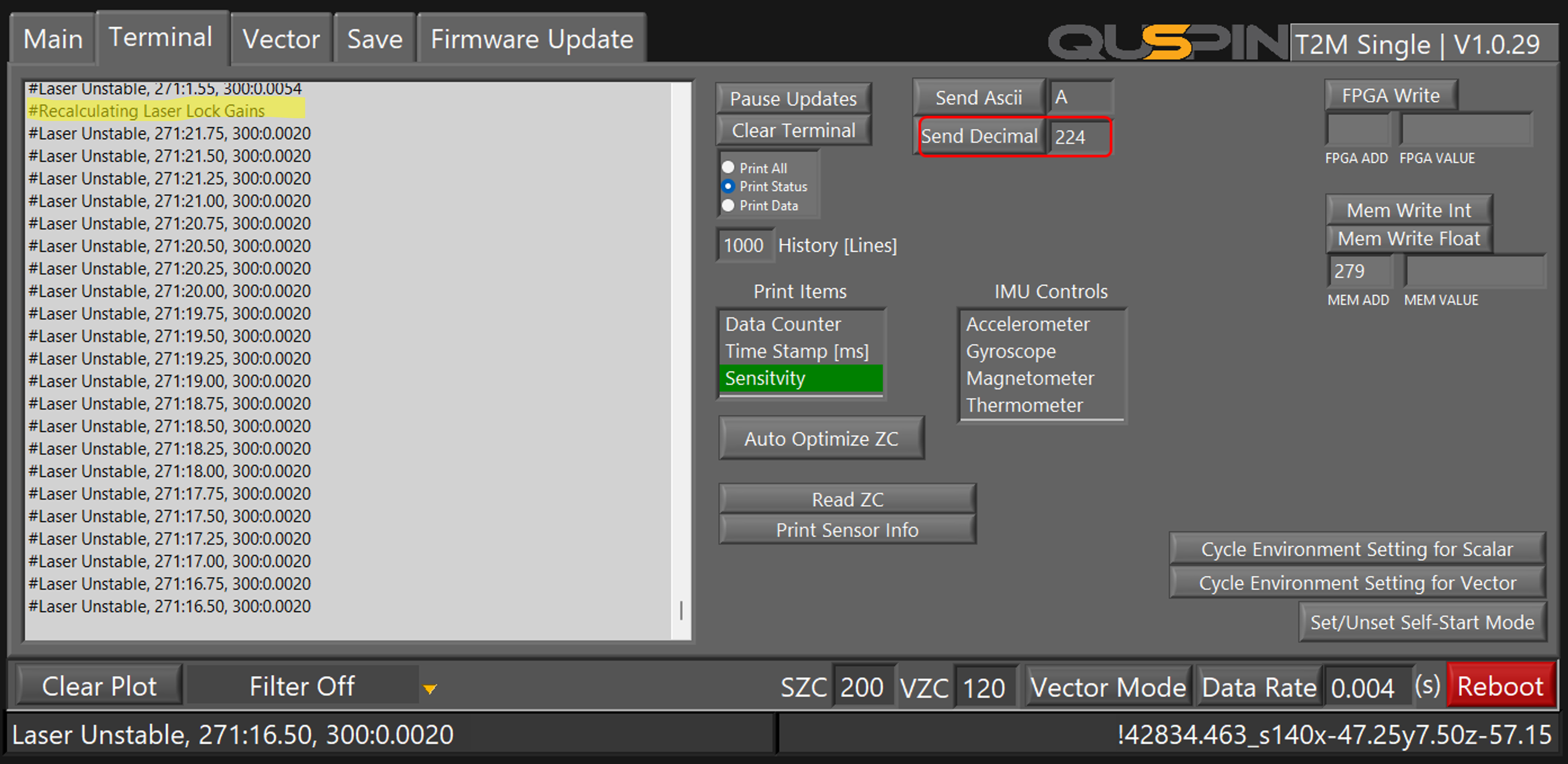
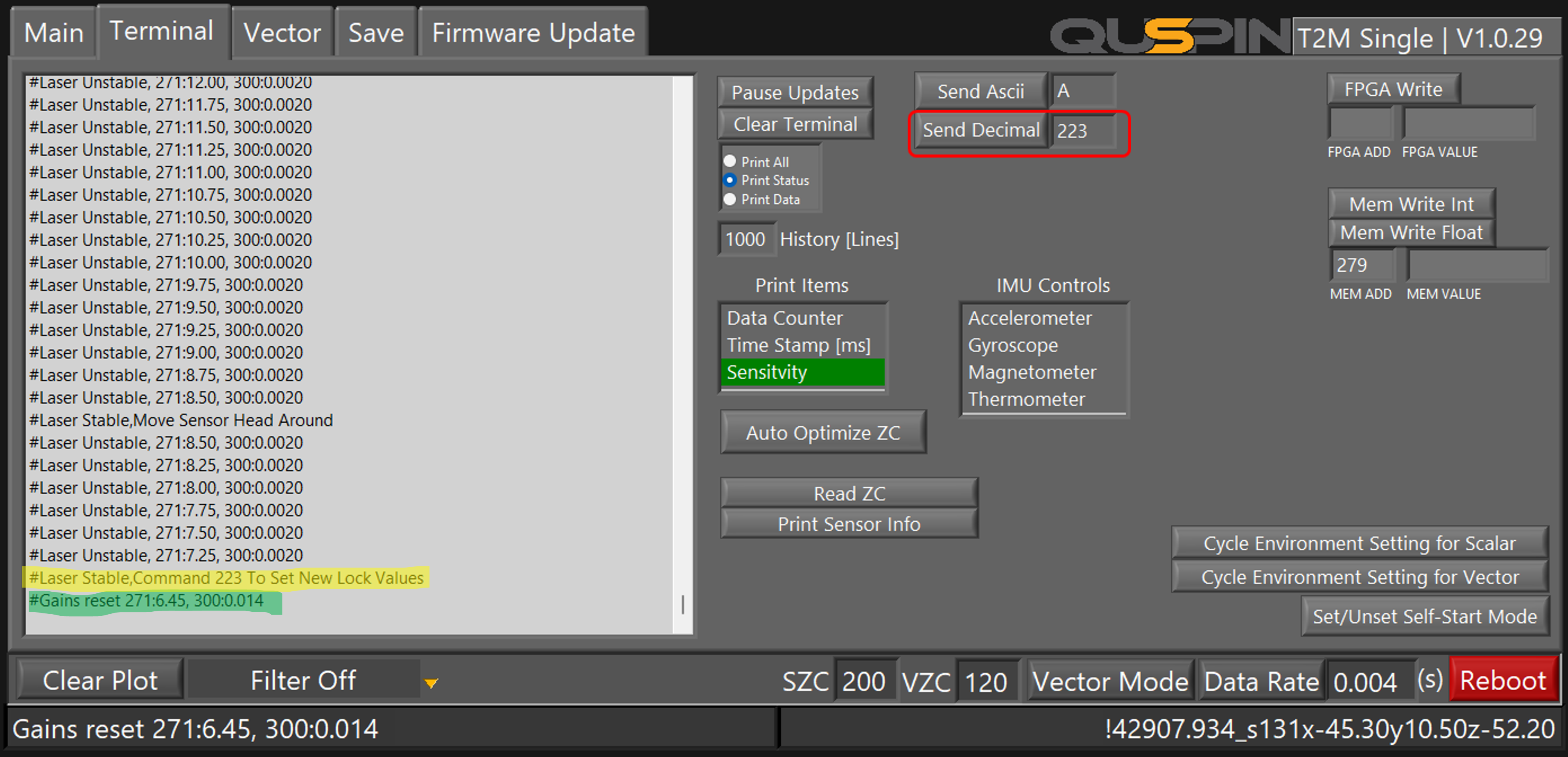
- Once no more laser unstable messages are being output on the terminal, you are ready to save the new gain parameters to memory. To do this Enter ‘223’ next to the ‘Send Decimal’ button and press it. Note, if no “laser unstable” message appears after the “#laser stable, move sensor head around” message after about a minute of moving the sensor head, proceed to send ‘223’ anyway to confirm the gains.
- Once no more laser unstable messages are being output on the terminal, you are ready to save the new gain parameters to memory. To do this Enter ‘223’ next to the ‘Send Decimal’ button and press it. Note, if no “laser unstable” message appears after the “#laser stable, move sensor head around” message after about a minute of moving the sensor head, proceed to send ‘223’ anyway to confirm the gains.
Resetting to Default Settings Step 0
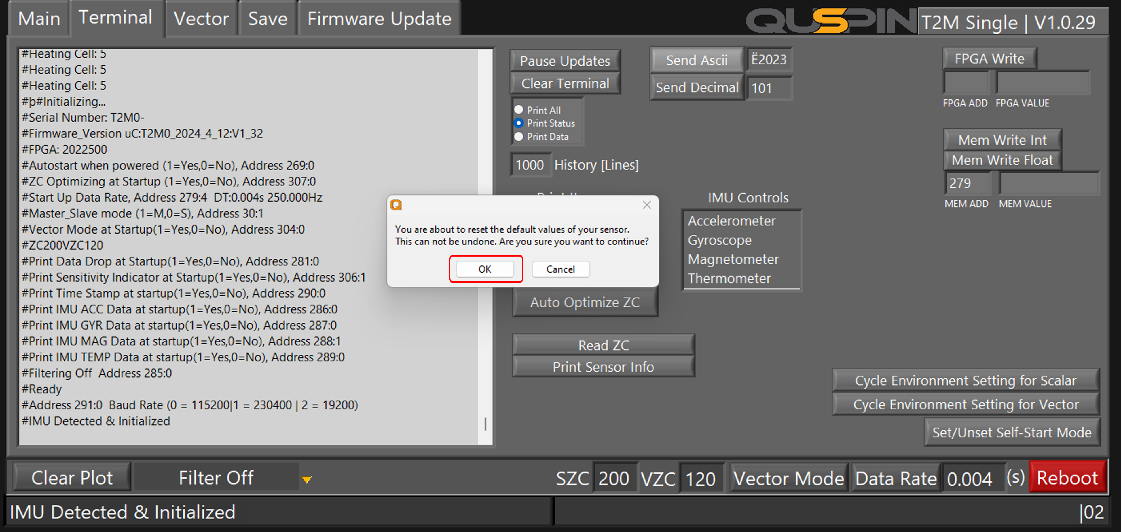
- Reset All Parameters:
- If you are not able to complete sections 1 and 2 or if the sensor is not not working as expected after re-optimization then you may need to reset the sensor to default parameters and re-optimize the sensor again.
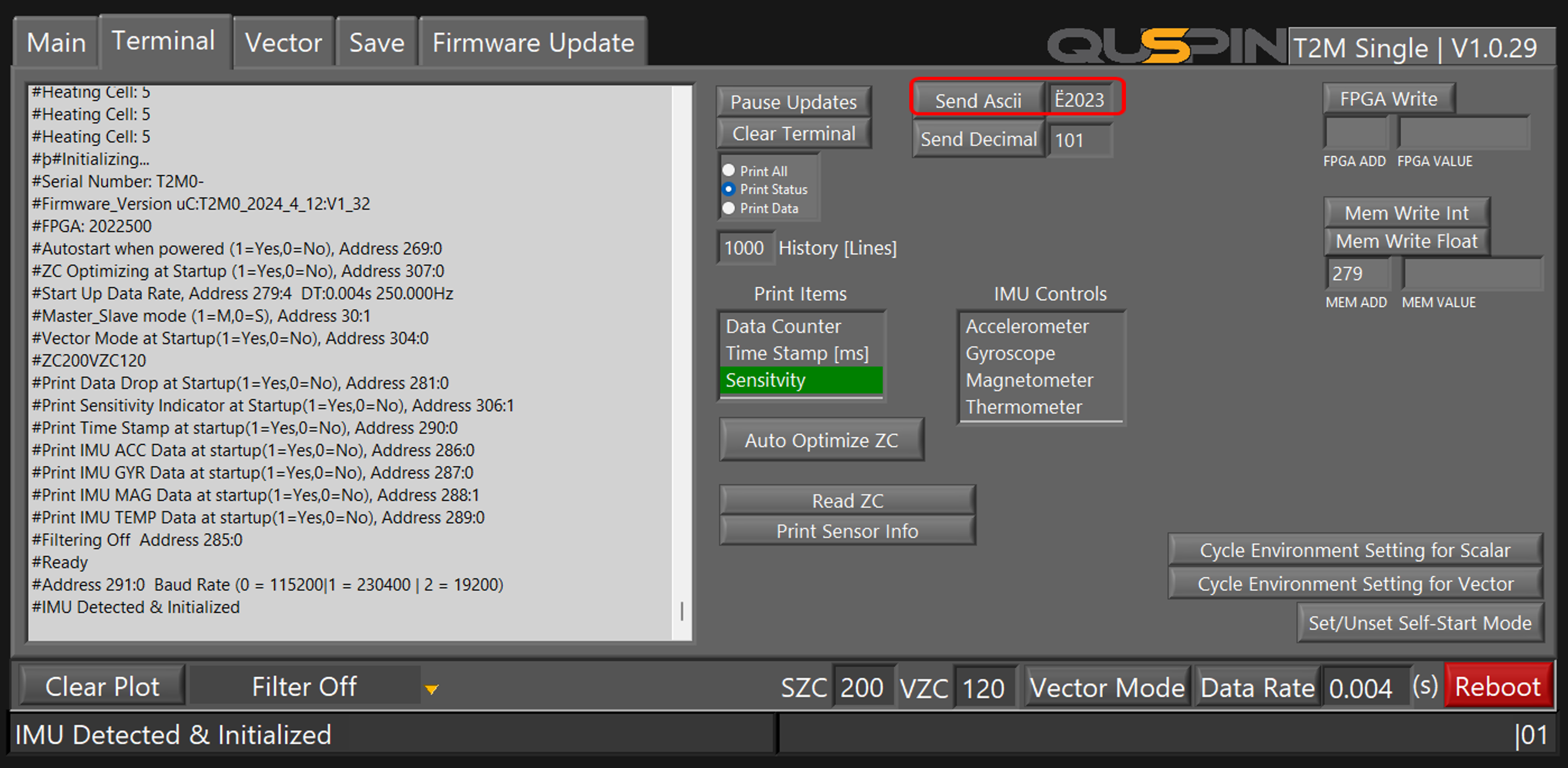
- To do this copy the ASCII string “Ë2023” and paste it into the textbox next to the ‘Send ASCII’ button, then click it. This will reset all parameters to their default settings.
- Following this reset, it is crucial to walk the sensor through the complete automated optimization procedure again to ensure all settings are correctly re-established. Section 1 and 2.
Completion
Upon completing these steps, your sensor should be fully optimized. This guide serves as a comprehensive resource for advanced users engaged in troubleshooting and optimizing Gen-2 QTFM sensors, facilitating the effective use of built-in firmware procedures. If the sensor is not able to complete the automated optimization process. Or if the sensor does not work as expected after running though steps please contact technical support for gen-2 QTFM sensor email jorton@quspin.com for further assistance.
