
QTFM sensor firmware vs. Magpie firmware This page covers the QTFM Gen-2 sensor firmware only — the microcontroller image that runs inside the sensor head and handles cell locking, magnetometer measurement, IMU integration, and sync. It does not update the Magpie / MiniACB logger firmware that wraps the sensor in a Magpie unit. The sensor and the logger have separate firmware images and separate update paths.
To update the Magpie / MiniACB logger firmware, see the Magpie Firmware Update Guide.
Important: set the Updater to 115200 for the update
The QTFM2 Firmware Updater talks to the sensor’s bootloader at 115200 baud.
This is independent of the sensor’s normal operating baud rate, which may be 921600 when used
with a Magpie. Selecting the sensor’s operating baud in the Updater prevents the bootloader
handshake and can produce an
Expected ACK (0xCC), got 0xF3 error.
Before you start the update:
- Confirm that the sensor works normally. Connect in the QTFM2 UI at the sensor’s usual operating baud, then close the UI completely so it releases the COM port.
- Set the QTFM2 Firmware Updater’s Baud dropdown to 115200 when you reach the Updater connection step below, regardless of the sensor’s configured operating baud.
If you see No ack (proceeding anyway) or
Expected ACK (0xCC), got 0xF3 in the Updater console, first confirm that the
Updater is set to 115200. See the
Troubleshooting section for the fix.
Important: put the sensor in idle mode before flashing
Flashing while the sensor is in autostart, locking, or actively measuring can cause the bootloader handshake to drop partway through the flash and leave the sensor in an unresponsive (“bricked”) state. Idle the sensor before clicking Program Firmware.
Two ways to do it:
- From the Updater: after you Connect, click the Disable auto-start mode button next to the Connect button. This is the easiest option and is built into the Updater for exactly this purpose.
- From a terminal: send
~Stop~over the sensor’s serial interface before launching the Updater.~Stop~halts any autostart / LI_Set / Reop / Warmup activity that’s currently in progress. (Requires sensor firmware V1_44 or newer.)
If a flash does hang partway and the sensor becomes unresponsive afterward, the Updater includes an Unbrick ECU recovery option — see the Troubleshooting section.
Which connection path?
The Updater itself is the same in both cases. The only difference is how you physically connect the QuSpin Standard Comms board to the sensor.
Path A
Sensor inside a Magpie
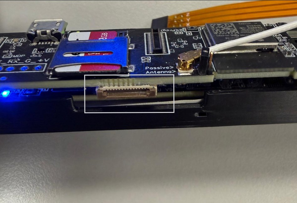
Use the flex-cable connector on the side of the MiniACB board.
- Sensor stays mounted in the Magpie sled
- Remove the outer Magpie shell to reach the flex connector on the side of the MiniACB board
- No need to disconnect or unmount the sensor itself
- Connect the Standard Comms board to that flex connector
- MiniACB V8 and later: the Magpie must be externally powered for the update
Path B
Bare sensor (no Magpie)
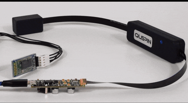
Connect the Standard Comms board directly to the sensor’s flex cable.
- For standalone sensors and dev / bench setups
- Connect the Standard Comms board directly to the sensor’s flex cable
- Same Updater, same procedure as Path A from this point on
Don’t have a Standard Comms board? One ships with every Magpie order (one per order, not per unit) and is available separately from QuSpin. Contact us if you need one.
Downloads
You need two files: the QTFM2 Firmware Updater (the Windows tool) and the encrypted firmware image for your sensor.
The Updater (Windows)
The firmware image
Verify the download before flashing
The SHA-256 for the V1_46 encrypted file is
DE32344CA0B7972716F310E4DD0CC0D86F092F1A5C23D1AF7DBA3D8CEA9D5521
(for the previous V1_45 file it is
8B8E82FF6BFCCE49494ED6F24968689B0CF7ED0DBA4D6C488726196366F7668A).
On Windows, open Command Prompt in the download folder and run:
certutil -hashfile T2M0_Firmware_V1_46.ino.EK-TM4C123GXL.bin.enc SHA256If the reported hash does not match exactly, re-download the file and do not flash it.
What’s new in V1_46
Improved vector accuracy on every sensor. We found that four of the six vector coil measurements were being compared against the wrong internal reference. This affected all sensors with the vector option, and it is corrected in this release. Your sensor repairs itself the first time it runs V1_46 — there is nothing to configure and no calibration step for you to perform.
Vector calibration now runs on the sensor itself. Previously the sensor applied three fixed correction values, and anything more accurate had to be applied afterwards in post-processing. V1_46 carries a full per-coil calibration and applies it live, so the data coming out of the sensor is already corrected. On our reference unit this reduced vector closure error from 281 nT to 16 nT.
New 500 Hz vector modes. Two new configuration profiles,
~V_500Hz_Pro_MP~ and ~V_500Hz_Robust_MP~, double the vector output
rate to 500 Hz total (166.7 Hz per axis). These require a 921600 baud connection, which means a
Magpie or an equivalent high-speed serial link. See the
Sensor Profile Configuration Guide.
IMU data no longer freezes. Under some conditions the sensor’s inertial measurement unit could stop returning new data while continuing to send packets, so the values would freeze at a constant or a plausible-looking reading rather than obviously failing. We traced this to the IMU’s serial interface being left in a mode where electrical noise from the vector coils could be misread as commands and corrupt its settings. V1_46 removes that mode; under test conditions that previously produced the fault every few seconds it no longer occurs. As a backstop, the firmware also detects a frozen IMU and recovers it automatically. If you use the accelerometer, gyroscope or IMU magnetometer outputs, we recommend this update.
Saved profiles in the Ultra Quiet vector environment. Loading a saved profile that had been stored in the Ultra Quiet environment set the vector measurement time slightly longer than the preset, which lowered the sensitivity indicator and could turn the status LED red until the environment was cycled. This is fixed: the sensor checks and corrects the stored value at start-up, and the start-up messages now state the vector measurement time and environment.
Vector measurement at the longest setting. On some sensors the Ultra Quiet vector environment (the longest measurement time) produced a low sensitivity indicator on one or two of the six coil measurements. The sensor now sizes each measurement to fit its own timing, so every coil measures cleanly; the other environments are unchanged.
Changing the data rate back to 1000 Hz now takes effect without a power cycle. Previously a sensor moved to 1200 Hz and back at runtime kept the 1200 Hz timing until it was power-cycled.
ECU identification at start-up. A sensor whose ECU generation has not been stored prints the command 249 identification report once at boot, so the information is in every log without having to ask for it.
Laser gain optimisation. ~Reop_Laser_Gains~ now shows the laser
lock error in place of the magnetometer data while it runs, the same display as command 136,
and restores the magnetometer output when it finishes. If the laser lock does not oscillate at
the first gain it moves to the higher gain automatically instead of waiting, and if it
oscillates at neither it finishes with the existing gains kept.
Improved sensor settings report. Command 7 no longer prints duplicate lines, and no longer reports power-supply values on sensors whose hardware does not measure them. On V10 electronics it now also records the input voltage and current seen during the last start-up and the lowest supply voltage the unit has ever seen, so a supply problem can be read back after the fact.
Quieter IMU status. An IMU that keeps recovering no longer prints a status line for every episode; after a few it prints one line saying further reports are suppressed. The magnetometer data is never affected by the IMU.
Settings are migrated automatically on the first boot after updating. No manual configuration steps are required.
What’s new in V1_45
- Fixes multi-sensor wired synchronization on sensors with older FPGA versions. Previously, sensors with pre-2026 FPGA firmware could report “Sensors Sync Complete” without actually resetting their timestamps. If you use wired master/slave synchronization, we recommend this update.
- Adds support for the new V10 ECU. The firmware automatically identifies which ECU generation it is running on; sensors with earlier ECUs are unaffected and require no configuration.
- On V10 ECUs, adds built-in health diagnostics: input voltage and current monitoring (decimal command 244), a power-supply quality check (decimal command 243), and a coil connectivity check (decimal command 242).
- Settings are migrated automatically on the first boot after updating. No manual configuration steps are required.
What’s new in V1_44
- Reliability fixes (2026-07-08 build). Faster automatic recovery from IMU read stalls with clearer status messages, stricter internal checks on direct settings writes (out-of-range addresses are now rejected with an error instead of being silently misapplied), and a fix that prevents a firmware update from unintentionally changing a saved vector timing setting.
- Custom user-saveable profile slots. Save up to three sensor configurations
to EEPROM with
~SaveSlot1~/~SaveSlot2~/~SaveSlot3~, switch between them with~LoadSlotN~, and list with~ListSlots~. See the Sensor Profile Configuration Guide for the full workflow. - Sensor-Only GPS Sync. The sensor now accepts the 11-byte UTC frame on its main UART, so non-Magpie hosts can drive GPS sync directly. See Method 4 in the Sync Guide.
- Integrator workflow tilde commands.
~Stop~to halt autostart / LI_Set / Reop / Warmup,~apply~to re-read EEPROM without rebooting,~Warmup~background pre-warmup,~ADDR,VAL~direct EEPROM write, and~report~to dump 28 key settings. These tilde commands bypass the ASCII command-lock so a locked sensor can still be reconfigured by an integrator host. - Better cold and hot laser autostart.
Wait_for_PD_signal()recovery loop rewritten with a trend-based heat/cool decision, wider entry condition, and a real heater escalation. Addresses the multi-restart symptom seen at sub-zero ambient and the lock-SP clobber seen at moderately cold ambient. - Watchdog tuned to thermal physics. Reload budget raised from 15 s to 50 s so legitimate long laser/cell autostart states do not trip spurious resets. Real hangs still recover in approximately 50–100 s.
- Boot-banner diagnostics.
#Reset cause (RESC): 0xNnow prints on every boot for unambiguous reset-source attribution (POR / brownout / WDT / SW). Sync-mode display on the boot banner fixed, and the_A/_Bsuffix on the#FPGA:line restored. - PPS realign hardening. Extended ISR_ERROR soak window after a PPS realign
suppresses the spurious
#ISR.Er4burst. The@NNNsample counter now stays continuous across realigns so multi-sensor data streams stay aligned.
Why is it encrypted?
The .bin.enc file contains the compiled QTFM Gen-2 sensor firmware encrypted
with a key that only the Updater knows. You don’t need to decrypt it manually —
the Updater handles that automatically when you flash.
If you need a specific older version, contact QuSpin. Some firmware revisions are sensor-specific or carry custom tuning, and we can send you the exact build for your unit.
Update procedure
These steps apply to both Path A (sensor inside a Magpie, via the MiniACB flex connector) and Path B (bare sensor, direct connection). The only difference is where the Standard Comms board plugs in.
Before you start
- QTFM2 Firmware Updater V1.1 downloaded to your PC (from the Downloads section above)
- The encrypted firmware image (
.bin.enc) downloaded to your PC (also from the Downloads section) - QuSpin Standard Comms board and a USB cable (data cable, not charge-only)
- The sensor powered, connected, and confirmed working in the QTFM2 UI before you start
- Path A with a MiniACB V8 or later: an external power supply for the Magpie. These boards must be externally powered for the firmware update to take place.
Steps
- 1 Connect the Standard Comms board.
Path A (sensor inside a Magpie): Remove the outer Magpie shell to expose the flex connector on the side of the MiniACB board (highlighted below), then plug the Standard Comms board into that connector. The sensor stays mounted in the Magpie sled — no need to disconnect or unmount it. On a MiniACB V8 or later, connect external power to the Magpie as well; the update will not take place without it.
Path B (bare sensor): Connect the Standard Comms board directly to the sensor’s flex cable, as shown below.
Plug the Comms board into a USB port on your PC. Windows should assign it a COM port number.
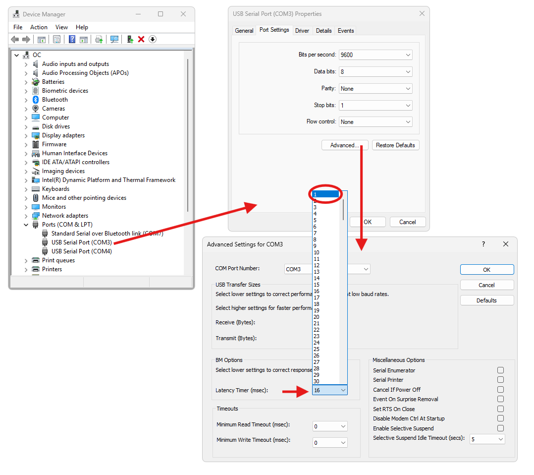
- 2 Identify and configure the COM port. Open Device Manager (search
“device manager” in the Windows search bar) and expand
Ports (COM & LPT). With the Standard Comms board plugged in, a new
COMNentry appears in the list — that entry is your sensor. Note the number; you’ll select it in the Updater at step 6.
Recommended: right-click that COM port → Properties → Port Settings → Advanced and set Latency Timer (msec) to1(the Windows default is16) for the fastest data transfer to the PC. This matters most for live streaming in the QTFM2 UI rather than for the flash itself, but it is convenient to set now while you are in Device Manager.
- 3 Confirm the sensor is communicating normally. Open the QTFM2 UI, connect to the sensor on the COM port you just identified, and confirm that its normal startup or measurement output is readable. This checks the cable, power, and COM port before flashing.
- 4 Close the QTFM2 UI completely. The Updater needs exclusive access to the COM port. If the QTFM2 UI is still holding the port open in the background, the bootloader handshake will fail even when the baud rate is correct. Close any other application that might have the same COM port open (PuTTY, Arduino Serial Monitor, etc.).
- 5 Launch the QTFM2 Firmware Updater. Run
QTFM2_Firmware_Updater_V1_1.exefrom the location where you saved it.
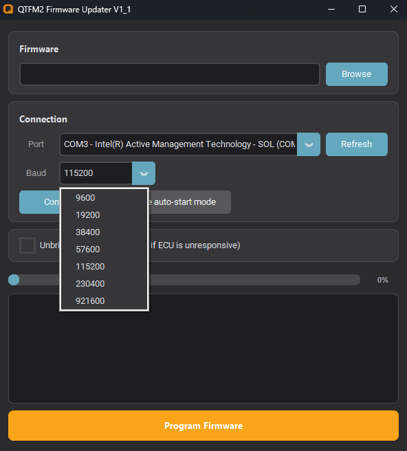
- 6 Select the COM port and set the baud rate to 115200. In the Connection panel, set
Port to the COM port for the Standard Comms board and set
Baud to
115200. Click Connect. The sensor’s normal operating baud does not apply to the bootloader used during the update. After connecting, click Disable auto-start mode so the sensor is idle before the flash begins. - 7 Browse to the firmware image. In the Firmware panel, click
Browse and select the
.bin.encfile QuSpin sent you. - 8 Click Program Firmware. The Updater will decrypt the
.bin.encfile, send the bootloader entry sequence to the sensor, erase the existing firmware, flash the new image, then verify and report success. The progress bar in the Updater shows the flash progress. Total time is typically 30 to 60 seconds. - 9 Power-cycle the sensor and confirm the update. Disconnect the sensor power, wait a few seconds, and reconnect. Open the QTFM2 UI, connect at the same baud rate as before, and look at the boot banner for the new firmware version line. If the version line shows the version you flashed, you’re done.
#Firmware_Version uC:T2M0_2026_9_22:V1_46Done The sensor is now running the new firmware. Its normal operating baud is unchanged by the bootloader’s 115200 update setting.
Frequently asked questions
After updating, command 244 says “V10 monitors not enabled.” Is something wrong?
No. Your sensor has an earlier-generation ECU, which does not include the monitoring hardware. The sensor operates normally; those diagnostic commands simply do not apply to it.
I sent a command while running a 500 Hz vector profile and nothing happened. Did the sensor stop responding?
No. At 500 Hz the sensor is spending most of its time formatting and sending data, and an
incoming command can be missed. This most often shows up when trying to leave the 500 Hz
profile. Send the command again — it usually takes on the second or third attempt.
Sending ~Stop~ first, then your command, is the most reliable sequence.
How do I check which firmware version my sensor is running?
Connect to the sensor with the QTFM2 UI (or a serial terminal set to the sensor’s operating baud), then power-cycle the sensor. Near the top of the startup banner, look for a line like:
#Firmware_Version uC:T2M0_2026_9_22:V1_46
The value after the final colon is the sensor firmware version; the preceding numbers are the
build date. The following #FPGA: line reports the separate FPGA bitstream version.
If QuSpin asks which version you are running, send both lines. Sensor firmware is customer
updatable; the FPGA bitstream can only be updated at QuSpin.
Some menu items in the QTFM2 UI do nothing. Is the software broken?
No. The QTFM2 UI and sensor firmware are released independently, and the UI presents the newest feature set. A sensor running older firmware may ignore commands behind newer menu items, so there is nothing for the UI to display. This most often affects Sensor Tune-up, Print Sensor Information, and parts of Advanced settings. Check the sensor firmware version as described above and update to the current release.
Troubleshooting
Updater console shows Expected ACK (0xCC), got 0xF3 (or similar non-0xCC byte)
This usually means the Updater was not set to the bootloader’s required 115200 baud. The line
just above it — No ack (proceeding anyway) — is the real failure point:
the Updater sent the bootloader ping and never received the expected 0xCC response.
Fix:
- Close the QTFM2 UI and any terminal that may be holding the sensor’s COM port open.
-
Re-launch the QTFM2 Firmware Updater, set the Baud dropdown to
115200, and Connect / Program Firmware again.
Updater shows garbage characters at the moment it connects
Confirm that the Updater is set to 115200, close all other applications using the
COM port, and reconnect. The sensor’s configured operating baud does not replace the
bootloader’s 115200 update rate.
Updater says it can’t open the COM port
Another application is holding the COM port open. Common culprits: the QTFM2 UI, PuTTY, the Arduino IDE’s Serial Monitor, or a previous Updater instance that didn’t fully release the port. Close all of them and try again. If the port still won’t open, unplug and replug the Standard Comms board to reset the USB connection.
USB port issues
A small number of users have hit framing errors on USB 3 ports that did not reproduce on USB 2. If the Updater is set to 115200, the QTFM2 UI is closed, and the handshake still fails, try a different USB port on your PC — preferably a USB 2 port if one is available.
The flash stopped partway through and now the sensor is unresponsive (“bricked”)
If the flash hangs or times out partway (for example, “stuck at 24%”) and the sensor stops responding to subsequent connect attempts, the Updater includes an Unbrick ECU recovery option for exactly this case. The Unbrick ECU checkbox sits between the Connect button and the progress bar. Check it when a normal Connect + Program Firmware run fails to recover an unresponsive sensor.
Recovery procedure:
- Close any other application that has the COM port open (QTFM2 UI, terminals, etc.).
- Re-launch the QTFM2 Firmware Updater, select the sensor’s COM port, and set the baud rate to 115200.
- Check the Unbrick ECU (check this box if ECU is unresponsive) checkbox.
- Click Browse and select the same
.bin.encfirmware file. - Click Program Firmware. The Updater runs an aggressive bootloader entry sequence to recover the sensor.
If Unbrick ECU still does not recover the sensor: confirm the Updater is at 115200, close everything else on the COM port, and try a different USB port (preferably USB 2). Also verify the sensor is getting a clean, stable power supply — an unstable supply or a USB hub mid-flash can hang recovery. If you are still stuck, send QuSpin the full Updater console output from the failed flash attempt and a description of when the sensor became unresponsive — we can usually diagnose the remaining cases from the log.
To prevent future ECU lockups: follow the two prep callouts at the top of this page — set the Updater to 115200 and put the sensor in idle mode before clicking Program Firmware.
Still stuck?
Send QuSpin a copy of the full Updater console output (from
Connected to COMN through the failure line) along with the sensor serial
number and the firmware version you are trying to flash. We can usually diagnose the remaining
cases from the console log.