
The vector coil attachment
An add-on three-axis coil attachment is needed for QTFM Gen-2 to output vector field measurements. The coil attachment slides over the sensor head and connects to the electronics controller with a flexible ribbon cable.
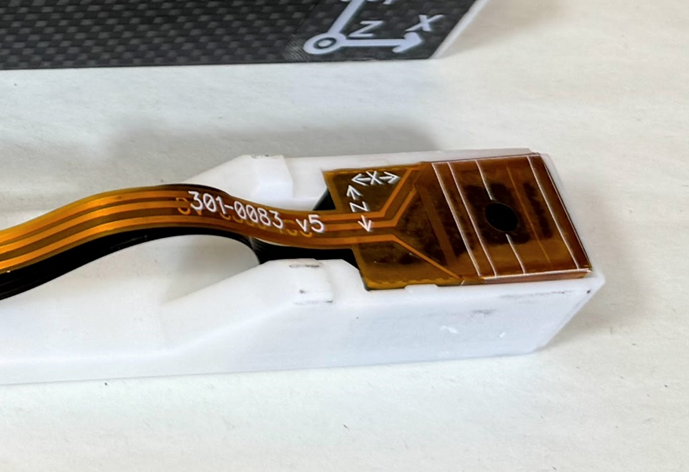
How vector mode works
QTFM is inherently a total field magnetometer and therefore it can only measure B0. However, with the coil attachment, QTFM G2 is sequentially subjected to pre-determined Bx, By, and Bz offset fields. From a measurement of the shift in B0 when the bias coil is on vs off, the vector components of the background field are mathematically calculated.
Interleaved timing and data rates
QTFM Gen-2 operates in a pulsed mode (link) in which one field measurement is made in a cycle that repeats every 1 ms. In scalar-only mode, a measurement of the total field [B0 = √(Bx2 + By2 + Bz2)] is made in each cycle. When the hybrid vector-scalar mode is activated, the total-field and vector components are measured in interleaved cycles as shown in the figure below.
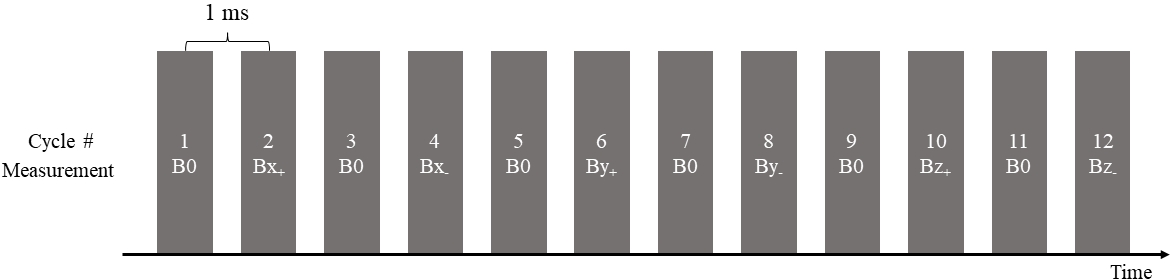
In cycles 1, 3, 5, … the sensor measures B0. In cycles 2 and 4, Bx coil is activated from which one measurement of the Bx field component is derived. Similarly, the By component is derived from cycles 6 and 8, and the Bz component is derived from cycles 10 and 12. Because each vector axis consumes a pair of cycles, vector output is inherently slower than scalar output — the trade-off for getting four measurements from one sensing region.
Maximum data rates. In scalar-only mode the sensor outputs as fast as 1 ms/sample (1000 Hz). In hybrid vector mode the fastest rates are 4 ms/sample for the scalar field and 12 ms/sample per vector axis.
Benefits & limitations
Benefits
- Compared to fluxgate, QTFM vector output is extremely stable with no noticeable long-term drift or temperature coefficient
- High sensitivity. Because each component is derived from the same scalar measurement rather than read off a separate sensing element, vector sensitivity tracks the scalar performance instead of being capped by a second, less sensitive sensor
- B0, Bx, By, Bz measurements from a single device and the same sensing region, so there is no baseline offset between the scalar and vector measurements
Limitations
- Designed for earth’s field operation, 1 µT to 200 µT
- Vector sensitivity degrades as the sensor head approaches a dead zone. See the dead zone guide for the affected orientations