
Serial port setup
This page provides information on communicating with the QZFM without using the QuSpin sensor UI.
This page last updated on March 15th, 2017.
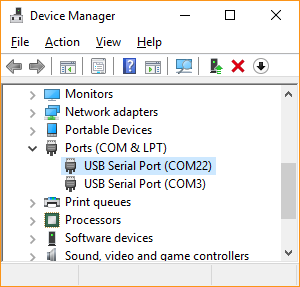
The QZFM electronics module can accept serial commands directly from a computer through its USB virtual Com port (USB-UART bridge) using any serial terminal emulator (such as Tera Term). The USB bridge uses the FT232RL chip. If drivers are not loaded automatically through Windows, they can be downloaded here.
Serial port settings
| Baud rate | 115200 |
| Data | 8 bit |
| Parity | none |
| Stop | 1 bit |
| Flow control | none |
Digital stream data types
The digital stream from the sensor electronics is classified into four data types, identified by the first character as described below.
| Prefix | Meaning |
|---|---|
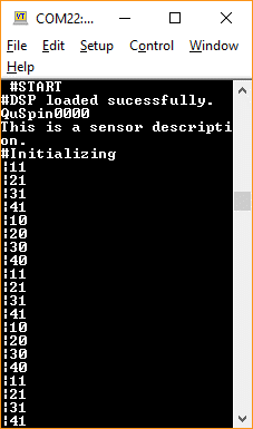
# | Sensor status and response messages from entered commands (as printed in the "Sensor Status" bar of the QuSpin sensor UI). Figure 1 shows the sensor stream during firmware boot up. |
| | LED indicators (|10 is Laser Off, |11 is Laser On, |20/|21 is Cell Temperature Lock Off/On, |30/|31 is Laser Lock Off/On, |40/|41 is Field Zero Off/On, and |50/|51 indicates Master/Slave sensor). |
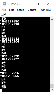
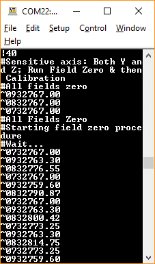
~ | Sensor parameter readout (~04 is cell temp error, ~05 is cell temp control voltage, ~07 is Bz field, ~08 is By field, ~09 is B0 field). To convert the raw field values, subtract 32768 from the 7-digit number following the two digit identifier. For example, ~0733582.50 = (33582.50 – 32768) = 814.5 pT applied Bz field. |
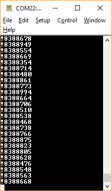
! | Magnetometer digital data output (24-bit numbers shown in Figure 5). To convert the raw output to pT, subtract 8388608 and then multiply by 0.01. For example, !8400953 = (8400953 – 8388608) × 0.01 = 123.45 pT. |
ASCII command list
The following table provides the ASCII command list for the QZFM (case sensitive).
| Command | ASCII | Decimal | Comments |
|---|---|---|---|
| Auto Start | > | 62 | Initiate the automated sensor startup routines |
| Field Zero ON | D | 68 | Start sensor field zeroing procedure to apply a compensation field using the internal sensor coils to null background fields (see Figure 4) |
| Field Zero OFF | E | 69 | Stop the sensor field zeroing procedure and holds the applied fields |
| X Y Z | i | 105 | In this mode, Field Zeroing is applied to all three axes (default) |
| Y Z | h | 104 | In this mode, Field Zeroing is applied only to Y & Z axes |
| Field Reset | V | 86 | Sets the internal coil field values to zero |
| Calibrate | 9 | 57 | Calibrate the response (field to voltage) of the magnetometer with an internal signal reference |
| Z-axis Mode | C | 67 | Operate the magnetometer in single Z axis mode |
| Y-axis Mode | F | 70 | Operate the magnetometer in single Y axis mode |
| Dual Axis Mode | B | 66 | Operate the magnetometer in dual Y and Z axis mode |
| 0.33x | a | 97 | Set the analog output gain to 0.33 times default (0.9 V/nT) |
| 1x | ` | 96 | Set the analog output gain to default (2.7 V/nT) |
| 3x | b | 98 | Set the analog output gain to 3 times default (8.1 V/nT) |
| Reboot | e | 101 | Reboot the microprocessor and reloads the firmware |
| Print ON | 7 | 55 | Turns on the sensor digital data stream and stops updating sensor status information (see Figure 5) |
| Print OFF | 8 | 56 | Turns off the sensor digital data stream and starts updating sensor status information |
Stream examples
Sending commands from the QuSpin UI instead? The command numbers are entered in the
‘Sensor Commands’ field described in the Quick Start Guide.