
Overview
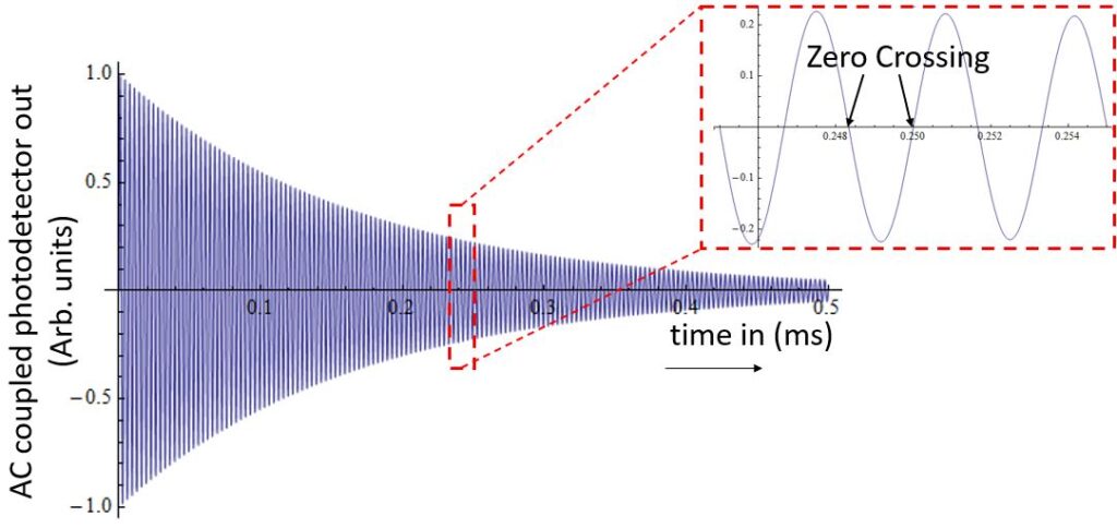
Fig. 1: The AC-coupled photodetector output of QTFM Gen-2 is a decaying sine wave (free induction decay). The rubidium precession frequency is determined from the time between zero crossings.
The raw, unprocessed QTFM Gen-2 signal is a decaying sine wave whose frequency is proportional to magnetic field. QTFM Gen-2 uses an internal frequency counter to measure this sine wave frequency and infer the magnetic field.
A key performance setting is the number of zero crossings (ZC) counted each measurement. This page explains:
- SZC: scalar-mode zero crossings
- VZC: vector-mode zero crossings
- Auto Optimization: automatically searches for an optimal ZC
- Vector Fixed Measurement Time (new): automatically adjusts VZC to keep the measurement time window approximately constant
Why adjust ZC?
In an ideal case, counting more zero crossings can improve sensitivity. However, because the sine wave decays exponentially, counting too many zero crossings can reduce signal quality and degrade sensitivity. The decay rate and amplitude depend on magnetometer orientation and gradients, so too many zero crossings can also increase dead zone behavior or increase susceptibility to gradient fields.
Consider changing SZC/VZC when…
- Too many bad data points → use fewer ZCs
- Need higher sensitivity → increase ZCs
Note After setting ZC, verify that the magnetometer can be subjected to the expected range of motion/orientation without bad data points. If bad data points appear, reduce ZC.
Preset environment settings
There are three pre-programmed ZC presets plus an Auto mode:
- Noisy Environment (lowest ZC)
- Smallest dead zone, highest gradient tolerance
- Sensitivity may be reduced
- Average Environment (mid ZC)
- Balanced sensitivity vs robustness
- Quiet Environment (highest ZC)
- Potentially highest sensitivity
- May increase dead zone / reduce gradient tolerance
- Auto Optimization (Auto)
- Searches for ZC that maximizes sensitivity
- Best for static applications
- Not recommended for mobile applications (can take a few seconds during which the magnetometer is unresponsive; may retrigger if bad points occur)
SZC and VZC can differ. Vector mode drives coils that can add gradient fields, so the optimal VZC is often smaller than SZC.
(Exact preset ZC values can vary slightly by firmware build; the terminal output always shows the active SZC/VZC.)
New: Vector Fixed Measurement Time mode (VZC time-base)
In addition to Noisy/Average/Quiet/Auto, vector mode now includes a Fixed Measurement Time option. In this mode:
- Scalar SZC is unchanged (stays at whatever SZC you set)
- Vector VZC is automatically computed from the measured vector frequency to keep the measurement time window approximately constant
- The firmware forces the computed VZC to round down to the nearest even value (implementation detail that improves consistency with zero-crossing counting)
Why use it?
Fixed measurement time is useful when you want consistent timing behavior across different magnetic field strengths (frequency changes), rather than a measurement window that grows/shrinks as frequency changes.
Time-base options (recommended defaults)
Vector Fixed Measurement Time cycles through these measurement windows:
- 100 µs (Noisy Environment)
- 200 µs (Average Environment) — recommended for most applications
- 300 µs (Quiet Environment) — recommended for most applications
- 380 µs (Ultra Quiet Environment)
- OFF (returns to standard Vector ZC presets / Auto Optimization)
Recommendation For most applications, 200 µs or 300 µs Fixed Measurement Time is highly recommended for vector measurements. These settings typically provide a strong improvement in vector sensitivity and reliability while maintaining robust performance across common operating conditions.
Notes
- Shorter windows (100 µs) can improve robustness in very noisy/harsh conditions but may reduce vector sensitivity.
- Longer windows (380 µs) can increase sensitivity in very stable conditions, but may be more prone to degraded reliability depending on gradients/orientation.
- Auto Optimization and Fixed Measurement Time are mutually exclusive (Fixed Measurement Time disables Auto Optimization).
Terminal output examples (Vector mode cycling)
When cycling Vector mode, the sensor prints status lines similar to:
#Vector ZC Auto Optimization Mode On
#Fixed Measurement Time Mode enabled, Noisy Environment(100uS)
#Vector Fixed Measurement Time Mode On!: 200uS,Average Environment
#Vector Fixed Measurement Time Mode On!: 300uS,Quiet Environment
#Vector Fixed Measurement Time Mode On!: 380uS,Ultra Quiet Environment
[Fixed Measurement Time: OFF -> Vector ZC Fixed:Noisy Environment]
This makes it easy to confirm whether you are in:
- Vector ZC fixed preset mode (Noisy/Average/Quiet),
- Vector ZC Auto Optimization mode,
- or Vector Fixed Measurement Time mode (100/200/300/380 µs).
Changing SZC/VZC from the UI or a terminal
Using the QTFM Gen-2 user interface
Open the Terminal tab and use the Cycle Environment Setting controls to cycle the scalar/vector settings. Selections are typically retained through reboot/power cycle (behavior may vary by firmware).
Using ASCII commands
You can also change settings via a serial terminal program:
| Decimal | ASCII | Command | Description |
|---|---|---|---|
| 106 | j | Environment Setting Vector | Cycles vector modes: Noisy → Average → Quiet → Auto → Fixed Measurement Time (100/200/300/380) → Fixed Time OFF → … |
| 107 | k | Environment Setting Scalar | Cycles scalar modes (SZC presets and Auto where supported) |
Tip After sending the command, the terminal prints the active SZC/VZC and a label indicating the current mode.
Setting custom ZC values (advanced)
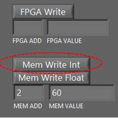
You can directly write custom SZC/VZC values via memory write:
- In the QTFM Gen-2 UI, open the Terminal Tab.
- Set SZC
- MEM ADD: 2
- MEM VALUE: (desired SZC)
- Press MEM Write INT
- Set VZC
- MEM ADD: 305
- MEM VALUE: (desired VZC)
- Press MEM Write INT
-
To retain these values after reboot/power cycle:
- Send Decimal: 105 (then press Send Decimal)
Important If Vector Fixed Measurement Time mode is enabled, the firmware will automatically update the effective VZC during vector operation to maintain the selected time base. To use a truly fixed custom VZC value, disable Fixed Measurement Time (cycle vector mode until Fixed Time is OFF).
To exit custom ZC selection mode and return to preprogrammed settings, cycle scalar/vector environment settings again (Decimal: 106 / 107).