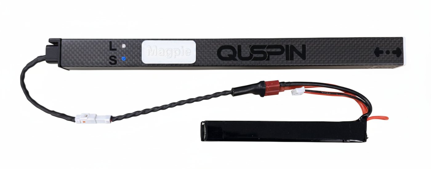
Field-ready quantum magnetometer system, built around the QTFM Gen-2 sensor.
Built for Breakthroughsquspin.com
Part I
Getting Started
1 Introduction
2 What’s Included
3 Setup
1
Introduction
Built for breakthroughs in geoscience, defense, and research.
Magpie is a compact, field-ready magnetometer system built around QuSpin’s QTFM Gen-2 sensor. It integrates a high-sensitivity magnetometer, GNSS, an IMU, onboard logging to an internal microSD card, and wireless connectivity into a single lightweight package.
Magpie can be operated using the Windows application over bluetooth for live plots, configuration, and data recording, or via a web browser over Wi-Fi through the MiniACB page for basic control and file access. For field use, the Magpie Android app provides a fast interface to send commands, view status, monitor real-time plots, and manage recordings from a mobile device.
Magpie also supports an optional vector add-on for triaxial (Bx, By, Bz) magnetic field measurements.
This manual covers setup, safe handling, connections, software operation, data stream format, hardware operation, technical reference and troubleshooting.
2
What’s Included
Contents may vary by configuration. Verify your shipment against the packing list. Many items can also be bought off the shelf; where possible, a vendor link is provided.
2.1 Standard Items (Typical)
Magpie Unit — the white plastic outer shell (the standard, default configuration) plus the internal sled and strain-relief hardware that the QTFM Gen-2 sensor is pre-mounted to. The shell, sled, and mounting hardware ship as one assembled unit. The white plastic shell is recommended over carbon-fiber for most applications because it offers better thermal regulation, stronger Bluetooth and Wi-Fi performance, and is transparent to GPS, allowing use of the internal GPS antenna without any additional accessory.
11.1 V (3S), 1800 mAh Li-Po battery pack (if ordered) — Battery weight 96 g. Approximately 4-hour operation time from full charge. Note: Any 11.1 V LiPo is compatible; the Magpie input range is +9.0–13.9 VDC. (Amazon)
Internal passive GPS flex antenna (SRFG017-100) — Pre-installed inside every Magpie. The standard plastic shell is GPS-transparent — an external antenna is only required for carbon-fiber shells or limited sky view. (DigiKey)
microSD card (32 GB, + SD adapter) — pre-installed for onboard logging and removable for offload (see Setup). Practically any 32 GB card works; a high-endurance card is recommended for sustained recording.
2-pin power cable terminated with the Magpie’s Julet connector on one end and a battery-pack connector on the other, plus a pair of spare male/female 2-pin connectors for repairs or rebuilds. (AliExpress)
2-pin + 6-pin breakout board (Julet M6 waterproof connectors) — The 2-pin cable carries battery power; the 6-pin cable breaks out the sensor serial UART (Rx/Tx), ground, and Sync_Input/Sync_Output. See Pinout in hardware.
Spare male/female 6-pin Julet M6 connector pair (for repair or rebuild of the breakout cable). (AliExpress)
The following ship once per order, not per Magpie:
11.1 V (3S) 1500 mA Li-Po battery charger (if battery pack is ordered) — Charges the included Li-Po pack from USB through its XH-4P balance connector. (Amazon)
Digital LiPo battery capacity / cell-balance tester (CellMeter-style, if battery pack is ordered) — Plugs into the battery’s balance lead. Used to confirm individual cell voltages and remaining capacity before each deployment. (Amazon)
Standard QuSpin Comms board — Used only to update the QTFM Gen-2 sensor firmware via the flex-cable connector on the side of the Magpie’s MiniACB board; it is not required for normal Magpie operation.
USB Wi-Fi dongle (TP-Link TL-WN725N, N150 nano) — Plug the dongle into your PC to associate with the Magpie’s Wi-Fi access point for the MiniACB browser interface, while leaving your PC’s built-in Wi-Fi free to stay on your normal network. (Amazon)
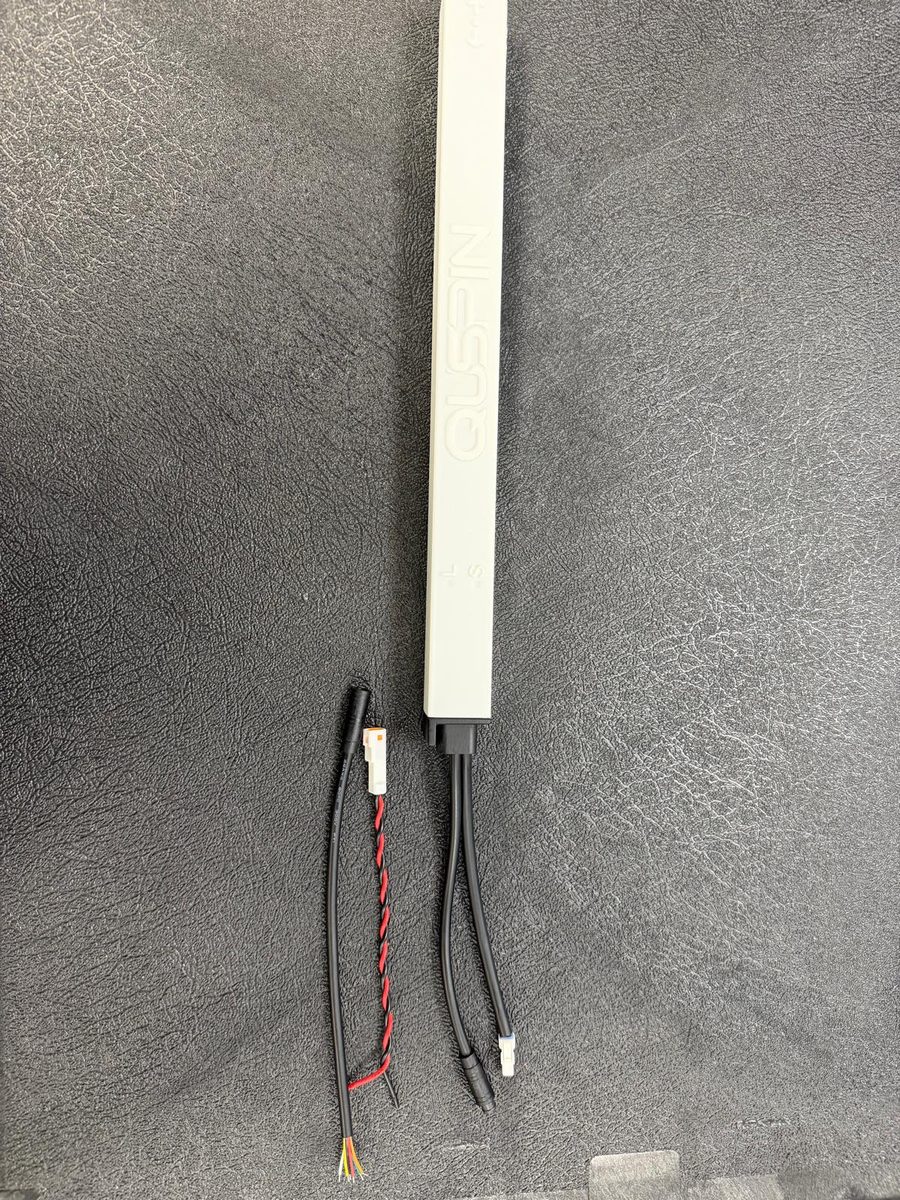
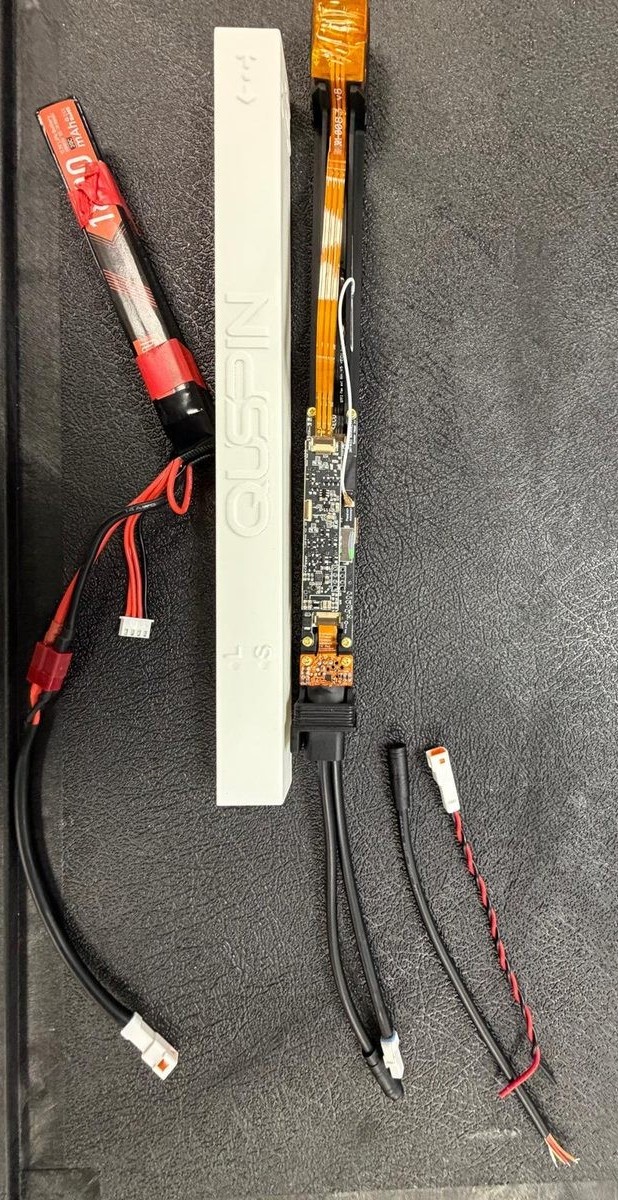
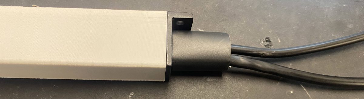
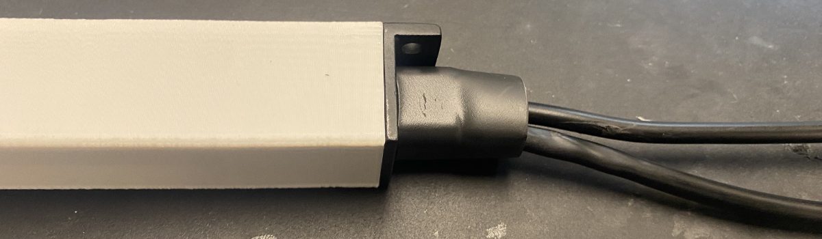
Standard Magpie kit. Left: the assembled Magpie in the white plastic shell (default configuration, QTFM Gen-2 sensor pre-mounted, internal GPS flex antenna pre-installed) with the 2-pin + 6-pin breakout cable that exposes battery power and the sensor’s UART / Sync lines. Right: the same unit with the shell removed, showing the internal sled and the QTFM Gen-2 sensor.
2.2 Optional Items
Vector add-on (triaxial Bx/By/Bz Magpie variant). The vector coils wrap around the standard single-axis sensor head. The vector-electronics board stacks directly on top of the Magpie electronics as an addition, not a replacement.
Carbon-fiber shell upgrade — Replaces the standard white plastic shell. Because carbon fiber attenuates GPS and degrades Wi-Fi/Bluetooth range, every carbon-fiber shell upgrade ships bundled with an external active GPS antenna (AN-GPS-A001-MMCX); the internal flex antenna is bypassed via the on-board jumper described in the GPS Antenna Guide. Choose this option only if you specifically need carbon fiber for mechanical, environmental, or aesthetic reasons; the default plastic shell is the recommended choice for most applications. External antenna (AN-GPS-A001-MMCX): DigiKey.
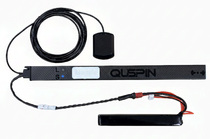
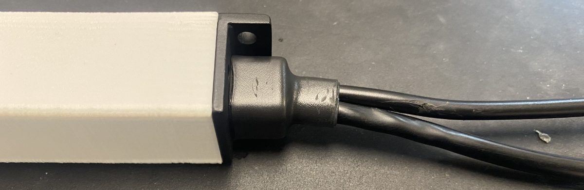
Optional carbon-fiber shell upgrade — shown with the bundled external GPS antenna. The upgrade replaces the white plastic shell and internal flex antenna for stronger sky view in vehicle-mount and field-survey use.
3
Setup
3.1 Quick Start (Bluetooth)
This quick sequence covers first power-up and a basic recording. For a video demonstration, see the online guide →
Wait for the Sensor LED to turn solid blue, indicating normal operation (see LED Codes).
Download and install the QTFM2 Windows application, then open it (see Software Installation).
Connect your computer to the Magpie over Bluetooth for control and live data (see Connecting to Bluetooth).
In the app, click “Connect” and select the Magpie by its serial number (about 10 seconds).
Verify live data in the user interface.
Click “Record” to set up a logging file, then “Start Recording” and let it run for a short test capture.
For Wi-Fi, see Connecting to Wi-Fi. A GPS lock can take several minutes; for the fastest lock, give the Magpie a clear view of the sky.
3.2 Initial Checks & Pre-Deployment Checklist
Every Magpie is tested before it ships, but a quick check before each deployment catches problems before they cost you data. To connect and start logging, see the online guide and quick-start video; the checks below confirm the unit is healthy and ready.
On Initial Power-Up
LEDs indicate full operation. The Sensor LED turns solid blue for valid data; the Logger LED must not be red. See LED Codes.
Autostart completes. In the QTFM2 software, watch for #Laser Lock Engaged → #Autostart Complete → #Cell Locked, in that order (see Status Message Reference).
If autostart stalls or the laser won’t lock, run Sensor Reoptimization.
No fault or warning messages. The terminal should be clear of error and stop-condition messages after boot. See Status Message Reference.
In the Field
Profile and settings are loaded. Confirm the sensor profile and output rate you intend for this survey (scalar vs vector, data rate). See the Sensor Profile Configuration guide.
GPS has locked. Give the Magpie a clear view of the sky; a 3D fix can take several minutes, GNSSFIX appears in the data stream. See GPS Antenna Guide.
SD card is ready. Confirm #SD card initialized successfully at boot and that there is room for the planned recording ([get_sd_card_info]). See SD Card Management.
If applicable: synchronization is verified (multi-unit). Verify the sync on each sensor before relying on cross-unit timing. See Time Synchronization.
3.3 Software Installation
Magpie supports three user interfaces: a Windows PC application, a browser-based interface hosted on the device (MiniACB over Wi-Fi), and an android app available on google play.
The QTFM2 UI Windows application provides live magnetic plots, a serial terminal for configuration, and recording and post-processing tools, while the Magpie Android app provides
a fast interface with similar functionality from a mobile device.
The MiniACB interface is a lightweight web page for basic status, a serial terminal, simple controls, and access to files stored on the internal microSD card.
Install the Windows Application
Download the latest QTFM Gen-2 User Interface from QuSpin.
Launch the installer and complete installation.
When Windows prompts, allow the application through Windows Firewall.
3.4 Connecting to Bluetooth
Magpie supports Bluetooth serial (SPP) for use with the Windows application.
Pair Magpie with Windows
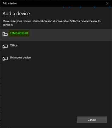
Open Windows Settings → Bluetooth & devices → Add device → Bluetooth.
Select the device that matches the Magpie serial number and complete pairing.
Changed the serial number? A serial-number change alters the unit’s Bluetooth identity, so Windows sees it as a new device. See Troubleshooting and FAQ for re-pairing steps.
Connecting Magpie to Bluetooth.
Note Bluetooth and Wi-Fi are mutually exclusive. To switch between connection modes, disconnect from the active connection or reboot the Magpie.
Improve Streaming Performance (Recommended)
Open Device Manager → Ports (COM & LPT) → select the Magpie outgoing COM port → Properties → Port Settings → Advanced.
Set “Receive Buffer” to the lowest setting to reduce apparent lag in live plots.
In the Windows application, select the Magpie outgoing COM port and confirm you see live data.
3.5 Connecting to Wi-Fi
Magpie provides a Wi-Fi access point for the MiniACB browser interface.
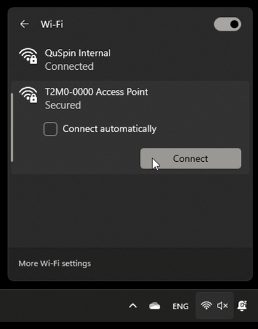
Open your device Wi-Fi settings and select the Magpie access point (SSID is typically the Magpie serial number).
When prompted, enter the default password: 12345678.
After connecting, open a web browser and navigate to http://miniacb/.
Note Your computer may show “No internet” while connected to Magpie Wi-Fi; this is expected. If your network does not resolve http://miniacb/, use the fallback IP address provided with your shipment.
Connecting to Wi-Fi.
Part II
Operation
4 Logging and Data Management
5 Time Synchronization
6 Data Output
7 Ethernet Operation
8 Firmware Updates
4
Logging and Data Management
Magpie logs data to the internal microSD card. You can start/stop logging and retrieve files using either the Windows/Android application (Bluetooth) or the MiniACB browser page (Wi-Fi), depending on your workflow.
Note When streaming data in real time over Bluetooth (rather than logging to the internal microSD card), packets are transmitted wirelessly and may be dropped if the Bluetooth connection is weak or unstable. For critical or high-integrity recordings, log directly to the internal microSD card.
4.1 Good Logging Practice
Wait for valid magnetic data before starting a critical recording.
Stop logging using the software controls before disconnecting power.
If the Logger LED indicates an SD-card or power issue, stop the run and correct the issue before continuing.
After each session, confirm your files are present and copy them to your computer for backup.
5
Time Synchronization
Magpie supports four sync modes depending on your deployment. Section 5.1 helps you pick one; subsequent sections cover each in detail. For step-by-step setup instructions and command sequences, see the published Syncing Your Gen-2 QTFM Sensors guide.
5.1 Choosing a Sync Mode
Mode
When to use
Key requirement
Section
Wired Master / Slave
Fixed arrays of 2+ Sensors with no external timebase.
Sync cable between units
§5.2
Wireless GPS sync
Standalone Magpie with internal GPS lock
GPS antenna, sky view
§5.3
PTP / IEEE 1588
Network has a PTP grandmaster
Ethernet to grandmaster
§5.4
External PPS
External GPS-locked PPS source
1 PPS input on Magpie
§5.5
NoteWireless GPS sync and External PPS sync both require the sensor’s FPGA bitstream at v5.05 or later.
The FPGA bitstream cannot be updated remotely — sensors purchased June 2026 or later ship with v5.05+ from
the factory; earlier units must be returned to QuSpin for the upgrade (contact info@quspin.com). After
the upgrade, the boot banner includes #FPGA 5.05 features. Additionally, Advanced Settings →
“Print Parameters” (or decimal command 7) will read #FPGA: 2026505. The wired Master/Slave method works on every
Gen-2 sensor regardless of FPGA version.
5.2 Wired Master / Slave
Two or more Magpies share timing over a physical sync cable with no external timebase or GPS required — the array agrees on a common cycle even indoors. Run a wire from the master’s Sync_Output (Green) to each slave’s Sync_Input (Orange) on the 6-pin breakout cable, and tie all grounds together. For the wiring pinout see the 6-Pin Breakout Cable chapter; for the command sequence see the Magpie Command Guide and the Syncing Your Gen-2 QTFM Sensors guide.
Backwards Compatibility Wired Master/Slave sync works between Magpies and classic QTFM sensors.
5.3 Wireless GPS Sync (Magpie → Sensor)
Each Magpie contains a single QTFM Gen-2 sensor, but multiple Magpies are often deployed together to form gradiometers, multi-axis arrays, or distributed surveys. Starting with the V1_43+ sensor firmware and the matching V10+ Magpie firmware, every Magpie can wirelessly time-align its sensor to absolute UTC using its on-board GPS — no shared sync cable required. Sensors in a wireless-synced array automatically lock onto the same UTC time base shortly after each Magpie’s GPS module acquires a fix, and stay locked for the duration of the log. Post-processing alignment then comes down to matching the UTC timestamps embedded in every line.
Requires FPGA bitstream v5.05+. Sensors built before June 2026 typically ship with an earlier bitstream and must be returned to QuSpin for the upgrade — it cannot be done remotely. See the full FPGA hardware requirement at the top of this chapter.
How It Works
The Magpie’s GPS module captures both an absolute UTC time and a hardware 1 Hz Pulse-Per-Second (PPS) signal. Once per second, the Magpie packs the current UTC time into an 11-byte frame (sync bytes 0xAA 0x55, an 8-byte UTC millisecond counter, and a CRC-8) and forwards it to the QTFM sensor over UART, timed off the PPS edge so the frame arrives with sub-microsecond jitter. The sensor (in GPS Sync mode, FPGA addr 30 = 3) realigns its internal cycle counter to that UTC reference, so every magnetometer sample is timestamped against absolute UTC. When the same reference is shared across multiple Magpies, all of their sensors converge to the same time base and the samples line up to better than a millisecond on every PPS edge.
Quick Start
The Magpie’s GPS receiver is off by default to save power. To bring up turnkey wireless sync, send two commands to the Magpie once (they persist across reboots): [GPS on] then [gps_sync_auto on]. In auto mode the Magpie waits for the GPS fix, polls the sensor until it is cell-locked, sends the sensor its sync commands, and begins forwarding UTC — you never send any commands to the sensor. The sequence is:
Position each Magpie under open sky and power it on.
Send [GPS on], then [gps_sync_auto on], over the Magpie’s Wi-Fi terminal, Bluetooth terminal, or USB console. Monitor progress with [gps_sync status].
Wait for the Logger LED to reach white (both GNSS and magnetic data present) and the Sensor LED to turn solid white — wireless sync is now active.
Start logging. All UTC timestamps embedded in the data stream are now common across every Magpie in the array, so post-processing alignment is a direct join on the UTC time base.
For step-by-step setup, the underlying sensor commands (cmd 113 to enter GPS Sync mode, 206 to enable, 209 to arm a one-shot lock, 230 for periodic re-arm on long runs, 231/232/233 to realign or disarm, 234 for the PPS status debug, 235 to toggle the LED between solid white and the troubleshooting rainbow), the External-PPS alternative, and a verification walkthrough, see the Syncing Your Gen-2 QTFM Sensors guide.
5.4 PTP / IEEE 1588
When the deployment network carries an IEEE 1588 grandmaster, the Magpie can discipline its clock to PTP over Ethernet. This path requires the W5500 Ethernet breakout board (see Ethernet Operation). Enable live with [ptp on] or at boot with [ptp boot on], and discipline the offset estimator to the GPS PPS edge with [ptp pps on] for sub-microsecond stability. See the PTP Time Synchronization commands in the Magpie Command Guide.
5.5 External PPS
For GPS-denied environments or arrays that share an external GPS-locked 1 PPS source, connect the 0–3.3 V PPS
line to every sensor’s Sync_Input (Orange) on the 6-pin breakout cable and tie all the grounds together.
No UTC is required — every sensor slaves its 1 Hz cycle to the shared hardware pulse. This mode requires
the sensor’s FPGA bitstream at v5.05 or later. See the Syncing Your Gen-2 QTFM Sensors guide for the wired External-PPS recipe.
Requires FPGA bitstream v5.05+. Sensors built before June 2026 typically ship with an earlier bitstream and must be returned to QuSpin for the upgrade — it cannot be done remotely. See the full FPGA hardware requirement at the top of this chapter.
5.6 Verifying Sync
Two quick visual checks confirm sync is live. (1) The Sensor LED is solid white whenever the sensor is GPS-wireless synced and the current measurement is good — this is the default. (2) For a per-second cross-sensor sanity check, send sensor command 235 to enable the troubleshooting rainbow: every Magpie in the array steps through Yellow → Green → Cyan → Blue → Purple in lockstep, one color per UTC second. The rainbow radiates a small 1 Hz magnetic signature, so revert to solid white (reboot the sensor, or toggle 235 again) before recording critical data. For a numerical confirmation, sensor command 234 enables a once-per-second debug line (#PPS dbg… edges= advancing, locked=1) that proves the sensor is actually receiving and edge-locking to the PPS reference.
Note
GPS lock requires clear line of sight to the sky. With the GPS receiver enabled [GPS on] and auto-sync armed
[gps_sync_auto on], sensors stay in their pre-sync state until each
Magpie reports its first GPS fix — sync then engages automatically.
6
Data Output
Magpie outputs an ASCII serial stream and logs it to a text file, where each line is one message (magnetometer samples, optional IMU packets, and GNSS fixes). Because these messages arrive as mixed line types, many post-processing tools work best if the data are converted into a clean, tabular CSV with a consistent time base. This chapter describes the line format and QLog_Processor, the QuSpin utility that turns a raw log into analysis-ready CSVs.
6.1 Data Structure
The Magpie logs every message from the QTFM Gen-2 sensor to an ASCII text file and augments the sensor’s native stream with two things: a high-resolution microsecond timestamp prepended to every line, and interleaved GPS position/time lines. The underlying sensor data format is identical to what the QTFM Gen-2 outputs natively — for the full sensor-level specification, see the QTFM Gen-2 Serial Communication and Data Format guide.
The Magpie Data Stream
Every line the Magpie outputs is prepended with a microsecond timestamp. After that timestamp, the first character identifies one of three line types:
After timestamp
Type
Description
! (exclamation)
Magnetometer
Sensor measurement data — scalar, vector, and IMU
# (hash)
Status
Sensor status and response messages
,GNSSFIX
GPS fix
GNSS position and UTC time from the Magpie GPS
,No GPS Fix
GPS no fix
GPS module has no satellite fix
Microsecond Timestamp
The Magpie prepends a microsecond timestamp to every line in the stream. For magnetometer data, the timestamp is captured when the sensor’s analog measurement pulse arrives; for GPS data, it is captured from the GPS module’s PPS (pulse-per-second) signal. Because both timestamps are triggered by analog pulses and not by the arrival of digital serial data, they are free from UART transmission delay and digital jitter, and are well suited to placing records in order and correlating them with GPS time. They remain the Magpie logger’s own clock, however — see below.
Which timestamp to use for timing
The millisecond timestamp is the QTFM’s standard timestamp — the
ms_ts field that follows > in the line format below. It is generated
by the sensor’s own clock, is jitter-free, and is the correct time base for any analysis
that depends on precise sample timing.
The Magpie’s microsecond timestamp (us_ts, at the start of each line) is added
by the logger. It is intended for correlating data with GPS time and for monitoring
dropped samples — not as the measurement time base. Using it as one is the most
common mistake we see in customer analysis. This applies equally to CSVs produced by
QLog_Processor and QLogMonitorConsole: take your time base from the sensor’s millisecond
timestamp column.
Why it exists. GPS data arrives asynchronously — the PPS edge does not line up with
the sensor’s measurement pulses, so neither can be timed by the other’s clock. Capturing
both on the Magpie’s clock, as described above, makes the microsecond timestamp the common
reference that places a magnetometer sample relative to a PPS edge and so gives it an absolute UTC
time. That is the job it does well. It is not derived from the sensor, so use it to
establish absolute time — not to measure the interval between samples, which is what
the millisecond timestamp is for.
Reading the timestamp There is no separator between the timestamp and the sensor data. The timestamp is simply all of the leading digits before the first non-digit character (! for magnetometer lines, , for GPS lines).
Magnetometer Data Line Format
The complete format of a Magpie magnetometer line, including the prepended microsecond timestamp:
All fields after the ! is produced by the QTFM Gen-2 sensor; the microsecond timestamp before the ! is added by the Magpie. Items in brackets are optional and depend on which print items are enabled.
Delimiter
Field
Example
Description
(none)
us_ts
368587947
Magpie microsecond timestamp (added by the Magpie)
!
scalar
51110.868
Scalar magnetic field |B| in nT (3 decimal places)
_ or *
sv
_
Scalar validation: _ = valid, * = invalid
X, Y, Z
vector
-18588.443
Vector component Bx, By, or Bz in nT
= or ?
vv
=
Vector validation: = = valid, ? = invalid
@
counter
046
Data counter (0–999, rolls over at 999)
>
ms_ts
367275
Sensor millisecond timestamp (ms since sensor power-on)
s
s_sens
112
Scalar sensitivity (0–999; 50+ is optimal)
v
v_sens
082
Vector sensitivity (0–999; 10+ is optimal)
Scalar validation. An underscore _ after the scalar value means the data is valid and reliable. An asterisk * means the data is likely invalid — common causes include the sensor oriented in a dead zone, an excessive gradient field, a background field outside the operating range, or an incorrect scalar zero-crossing (sZC) setting.
Vector validation. An equals sign = after the vector value means valid data; a question mark ? means invalid data — common causes include the sensor oriented in a dead zone, excessive gradient field, and incorrect vector zero-crossing (vZC) setting.
Vector axis cycling. Only one vector axis (X, Y, or Z) is printed per line. The three axes cycle sequentially on consecutive lines, so the vector data rate is 3× slower than the scalar data rate.
Data counter. A three-digit counter (0–999) that increments with each data point. A gap greater than 1 between consecutive values (except at the 999→0 rollover) indicates dropped data.
IMU Data
When an IMU control is enabled, one IMU packet is appended to the end of the magnetometer line. Each IMU type uses its own set of delimiters:
IMU type
Delimiters (X, Y, Z)
Example
Accelerometer
a, b, c
a-739.75b55.18c-703.12
Gyroscope
i, j, k
i20.34j-37.74k24.27
Vector magnetometer
x, y, z
x-8.70y36.15z-31.05
Temperature
t
t68.09
All three axes for a given IMU type are printed together on the same line. When multiple IMU types are enabled, they alternate on consecutive data lines.
Two vector magnetometers The IMU vector magnetometer (lowercase x, y, z delimiters) is a separate, low-precision sensor from the QTFM’s primary vector add-on, which uses uppercase X, Y, Z.
IMU Location The IMU is mounted on the Magpie ECU — For instance, the IMU's temperature data refers to ECU/MiniACB temperature.
See Figure for details.
GPS Data Lines
When the GPS module has a fix, the Magpie interleaves GNSS fix lines into the stream (typically once per second). A GPS line uses a comma as its first character after the timestamp:
When there is no satellite fix, the line is simply:
{us_ts},No GPS Fix
Field
Description
lat
Latitude as an integer (decimal degrees with the decimal point removed)
lon
Longitude as an integer (decimal degrees with the decimal point removed)
year, month, day
UTC date
hour, min, sec
UTC time
alt_m, alt_dm
Altitude in meters and decimeters
Time Synchronization Between GPS and Magnetometer
The microsecond timestamp is the key to relating GPS time to magnetometer time. Both line types share the same Magpie microsecond clock, and — critically — both timestamps are captured from analog pulse signals: the sensor’s measurement pulse (IO22) for magnetometer data, and the GPS module’s PPS pulse for GPS data. The timestamp records when each pulse fires (when the measurement is taken), not when the subsequent digital data is received, which eliminates UART transmission delay and digital jitter from the timing.
This means you can:
Use the ,GNSSFIX line to get absolute UTC time and position.
Use the shared microsecond timestamp to precisely correlate each magnetometer reading to the GPS time base.
Interpolate GPS position at any magnetometer sample time, since both reference the same clock.
Worked Example: A Complete Data Stream
Below is real Magpie output showing magnetometer lines with alternating IMU packets (gyroscope and accelerometer) and one interleaved GPS fix line:
Note The data counter (@) is absent from this example because it was disabled for the capture. When enabled, it appears between the vector validation character and the > timestamp delimiter — for example =@046>367275.
Magpie microsecond timestamp (same clock as the mag data)
GNSSFIX
GPS fix identifier
399652672
Latitude (integer representation of decimal degrees)
-1051083328
Longitude (integer representation of decimal degrees)
2025,09,16
UTC date: September 16, 2025
19,21,26
UTC time: 19:21:26
1615,6
Altitude: 1615 m, 6 dm
Because the magnetometer line (368587947) and the GPS line (368711323) share the same microsecond clock, this GPS reading was captured 123,376 µs (about 0.12 s) after the first magnetometer reading shown. That shared clock is what enables precise correlation between GPS position/time and magnetometer measurements.
QLog_Processor is the post-processing utility for Magpie logs; it replaces the previous flat-formatter to interpolation workflow. Drag a raw .txt log onto the executable and it writes its output into the same folder as the source log. A single pass produces four products, each named after the source file:
Output
What it is
<name>_flat.csv
Flat reformat. Each raw line becomes one row under a common column set — a direct, lossless reformat with no interpolation. Magnetometer rows carry the mag fields, GPS rows carry position/UTC, and columns that do not apply to a given row are left blank. Best for quick inspection and scripting.
<name>_dedup.csv
Deduplicated. A consolidated table in which each sample row also carries its associated GPS position and UTC time (native sample times, not resampled), so every row is fully populated.
<name>_interpolated.csv
Interpolated — the analysis-ready product. Resampled onto a uniform millisecond time grid, with all three vector axes, IMU, and GPS fields filled per row so downstream tools see one continuously populated table.
<name>_summary.txt
Run summary. Human-readable: total rows, start/end UTC, total elapsed time, the sample interval (dt), and any status messages found in the log.
The three CSVs share one column schema:
|Timestamp(uS)|SensorTimestamp(ms)|MagData(nT)|Good S - Data|Data Counter|

|Scalar Sensitivity|bX(nT)|bY(nT)|bZ(nT)|Good V - Data|Vector Sensitivity|

|Latitude | Longitude | HAE(m) |UTC Date (YYYY-MM-DD)|UTC Time (H:M:S.mS)|

|AccelerometerX(mg)|AccelerometerY(mg)|AccelerometerZ(mg)| GyroX | GyroY |

| GyroZ | IMU_VMagX (uT) | IMU_VMagY (uT) | IMU_VMagZ (uT) | IMU_Temp(C) |
DownloadQLog_Processor.exe (Windows, 7.0 MB, no installation, updated 2026-10-09) converts a raw log into the CSV set described above. The same tool is also published as a single Python file, Qlog_ConverterV5.py (standard library only, Python 3.9 or newer: py Qlog_ConverterV5.py yourlog.txt), for anyone who wants to read it, check it, or run it on a machine that is not Windows; the executable is this file packaged with PyInstaller. Check a download before you rely on it — SHA-256 0f8c059d4de6b5ebe79f3e1c70eddf062ac3f9ff1f4006ee6701bf0e5babb4e5 for the executable and b8856f9cebd4f5b20ac9e775573d002d86b6658abe6944971ec9a9a5988c5381 for the source.
Updated 9 October 2026 The UTC time column now carries milliseconds, under the header TimeUTC(HH:MM:SS.sss); earlier builds printed whole seconds. The data counter and the two sensitivity indicators are no longer interpolated between measurements. A log containing a truncated line no longer stops the conversion. A line whose timestamp does not belong with the lines around it is discarded and reported instead of being used, and rows stamped exactly zero at the start of a session are dropped; the summary file lists every row removed this way. The converter now refuses to build a time axis it cannot support, and says so. All of these were reported by users — if you are running a build dated before this one, replace it.
7
Ethernet Operation
Hardware requirementEthernet operation is not part of the standard Magpie package. It requires an additional W5500 SPI Ethernet breakout board that mounts to the Magpie and exposes an RJ-45 jack. Order this separately from QuSpin if your deployment needs wired streaming, low-latency PTP synchronization, or LCM-format publishing to an ASPN subscriber. The procedure and commands in this section have no effect on a stock Magpie.
With the breakout board installed, the Magpie can stream sensor data over Ethernet via TCP on port 5000, accept commands inbound on the same connection, and publish in ASPN/LCM formats to a remote subscriber. Up to four simultaneous TCP clients are supported, plus an optional UDP data port on 9000 for data-only output. Ethernet is more reliable than Bluetooth or Wi-Fi for sustained high-rate streaming and is the recommended interface for survey-grade work and any deployment with PTP-synchronized post-processing.
7.1 Default Network Settings
Out of the box, the Magpie is configured as IP 192.168.10.2, subnet 255.255.255.0, gateway 192.168.10.1. The TCP data port is 5000 and the optional UDP data port is 9000. Set your PC to a static IP on the same subnet (for example 192.168.10.1) and connect a standard Cat5e or better Ethernet cable directly between the PC and the Magpie — the W5500 auto-detects polarity so no crossover cable is required.
Change the Magpie’s IP, subnet, or gateway with [eth ip …], [eth subnet …], and [eth gateway …] respectively (saved to NVS; reboot to apply).
7.2 First-time Setup
The Magpie’s GPIO IO20 is shared between the external serial port and the W5500 SPI bus, so the external serial path must be disabled before Ethernet can come up. Connect via USB serial or Bluetooth (you only need this once), then send [serial port internal], then [mode ethernet], then [reboot] to apply. After the reboot, the Magpie comes up in Ethernet mode and the boot banner shows the link state and assigned IP. Verify with ping 192.168.10.2 from your PC (replies should arrive in roughly 1 ms). The [eth status] command reports the running configuration and connected-client count.
7.3 Python Connection Tool
QuSpin ships a small command-line tool, mini_acb_ethernet.py, in the firmware repository’s tools/ folder. It connects to the Magpie over TCP, can log incoming data to a timestamped file, optionally parses binary packets, and runs PC-side ASPN conversion. Python 3.6 or later is required; no third-party packages are needed (standard library only). Typical usage:
python mini_acb_ethernet.py
connects to 192.168.10.2:5000 in quiet mode. Useful flags: --data (show every data line), --log (immediately start logging to a timestamped file), --binary (parse binary packets — use when [eth binary on] is set on the Magpie), and --aspn [--aspn-version 2023|3.0] (run ASPN conversion on the PC side, the recommended path in binary mode). Once connected, anything typed at the prompt is routed to the Magpie just like Bluetooth or USB Serial.
7.4 ASCII vs Binary Data Formats
By default the Ethernet stream is ASCII text, identical to what you would see on Bluetooth or USB Serial — see the Data Output chapter for details. Switch to binary with [eth binary on] when bandwidth is constrained or you want a fixed, parser-friendly packet shape. The binary packet layout is:
Byte count of the timestamp + payload (little-endian)
ts_us_LE
8
Local microsecond clock timestamp
payload
N
The data line (magnetometer or GPS)
xor_chk
1
Checksum XOR of the type byte, both length bytes, and the entire payload
Note Status messages (#-prefixed) are still sent as ASCII even in binary mode — the binary framing only wraps data packets.
7.5 ASPN Output
ASPN (Airborne Survey Protocol for Navigation) is a YAML-based standard format for magnetometer survey output. Enable on-device ASPN conversion with [aspn on] (ASCII mode only). For binary mode, run the conversion on the PC side via the Python tool’s --aspn flag — this avoids the bandwidth and on-device CPU cost of multi-line YAML inside the binary packets. GPS position publishes as an ASPN GeodeticPosition 3D record (ICD 1001.3), including altitude; a legacy 2D format is available via [gps_format 2d].
7.6 Ethernet Troubleshooting
If ping fails: verify the cable, confirm the PC’s IP is on the same subnet, and check that the serial port was set to internal before Ethernet boot. Boot banner showing ETH HW: NoHardware means the W5500 was not detected on the SPI bus — usually an IO20 conflict (re-send [serial port internal] and reboot) or a hardware issue with the breakout board. ETH LINK: DOWN means no cable or a faulty cable. Connections that drop briefly right after a command are expected; the Python tool reconnects automatically.
8
Firmware Updates
There are two updatable firmware images inside every Magpie which update independently. The Magpie / MiniACB logger firmware (Wi-Fi, Bluetooth, SD card, Ethernet, etc.) is updated from the Magpie itself; the QTFM Gen-2 sensor firmware is updated through a flex-cable connector on the side of the MiniACB board using a standard QuSpin Comms board. The two procedures use different files and different cables — check which firmware QuSpin has asked you to update before starting.
Always use the latest firmware The downloads and step-by-step procedure for both methods below live in the Magpie Firmware Update Guide. The page is updated every release, so even if these steps fall behind, the linked guide will have the current MINI_ACB_V<N>.ino.bin and .merged.bin files plus any release-specific notes.
8.1 Updating the Magpie / MiniACB Logger Firmware
The logger firmware can be flashed two ways: Wi-Fi OTA (recommended for most users) or a USB UART flash using ESP32_Flasher.exe (a recovery path that works even when Wi-Fi is unavailable).
Method 1: Wi-Fi OTA (Recommended)
Power the Magpie on and connect your computer or phone to the Magpie Wi-Fi access point (default password 12345678).
Open a web browser to http://miniacb/ and scroll to the firmware upload section at the bottom of the page.
Click Choose File and select MINI_ACB_V<N>.ino.bin (no need to rename the file).
Click Upload. Wait for the upload to finish, then send [update] from the page’s logger-command panel to apply the update and reboot.
Method 2: USB UART Flash (Recovery)
If the Wi-Fi OTA path is unavailable (first time setup, recovery from failed OTA, or as release notes specify), use the ESP32_Flasher.exe
Windows tool over the Magpie’s USB port.
Connect the USB cable, launch the flasher and connect to the new COM port.
Configure the flasher window:
.bin — select MINI_ACB_V<N>.ino.merged.bin
Flash Address — set to 0x0 - Merged all-in-one firmware (bootloader+part+app)
Baud Rate — leave at 921600 (default)
Click ”Flash ESP32“ and wait. Once --- Finished --- appears, disconnect.
Open the QTFM2 UI, http://miniacb/or any serial terminal and send the string [refresh_sn]. You will see an output like: #Serial Number: T2M0-00NB
Notes
[refresh_sn] renames the Magpie’s Bluetooth and Wi-Fi identity. To reconnect, first remove
the old Bluetooth pairing or the forget previous the Wi-Fi network, then follow the connection steps in Setup.
MiniACB firmware V5_10+ only If the sensor LED shows connected (blinking blue) but the startup banner doesn't appear, then
[refresh_sn] may have run automatically after the flash. Disconnect and reconnect to the Magpie.
App-only UART flash You can flash the smaller
MINI_ACB_V<N>.ino.bin at 0x10000 - App binary (Arduino / PlatformIO default),
which updates the firmware while preserving the Magpie’s saved preferences. No refresh_sn
step is need afterwards.
Do NOT use this path to recover a bricked unit — the App-only image doesn't include the bootloader or
partition table, so a corrupted bootloader will still leave the unit unable to start.
The QTFM Gen-2 sensor that lives inside the Magpie has its own firmware, separate from the MiniACB logger. It is not flashed over Wi-Fi or USB; instead, every MiniACB board exposes a small flex-cable connector on its side that connects directly to the sensor’s programming pins. Plug a standard QuSpin Comms board into that connector and update the sensor firmware exactly as you would on a bare Gen-2 sensor. You will need to remove the outer Magpie shell to reach the connector, but the sensor itself stays mounted in the internal sled throughout.
Before you flash Put the sensor in idle first (send ~Stop~, or disable auto-start) so it is not streaming during the update, and make sure the QTFM updater’s baud rate matches the sensor’s. A baud mismatch is the most common failure — it shows up as Expected ACK (0xCC), got 0xF3.
Procedure (Summary)
Power off the Magpie and remove the outer shell so the MiniACB board is accessible. The sensor itself stays mounted on the internal sled — do not separate it from the sled.
Connect the standard QuSpin Comms board to the flex-cable connector on the side of the MiniACB board
(see Everyday Operation).
Note Older sled versions will require the MiniACB be unscrewed to access the connector.
Plug the Comms board into your PC over USB and follow the QTFM Gen-2 firmware update procedure. The Magpie’s logger does not need to be running during this process; the sensor is reflashed directly through the Comms board.
Disconnect the Comms board, slide the sled back into the shell, and power the Magpie on. The new sensor firmware version appears in the boot banner.
Online guide A video of the QTFM2 sensor update is in the online guide →
Part III
Hardware
09 Everyday Operation
10 Magpie Assembly
11 6-Pin Breakout Cable
12 Integrating Alternate Cables
13 GPS Antenna Guide
09
Everyday Operation
Routine hardware tasks you will perform in the field: powering the Magpie from its battery, opening the outer shell, and removing the SD card.
9.1 Battery Operation
WarningThe Magpie is powered by a lithium-polymer (LiPo) battery. Do not puncture, crush, short, or expose it to water or excessive heat. Charge only with the supplied charger, do not leave it charging unattended, and avoid charging and discharging the battery simultaneously. Stop using any pack that is swollen, damaged, or hot — damaged LiPo cells can catch fire.
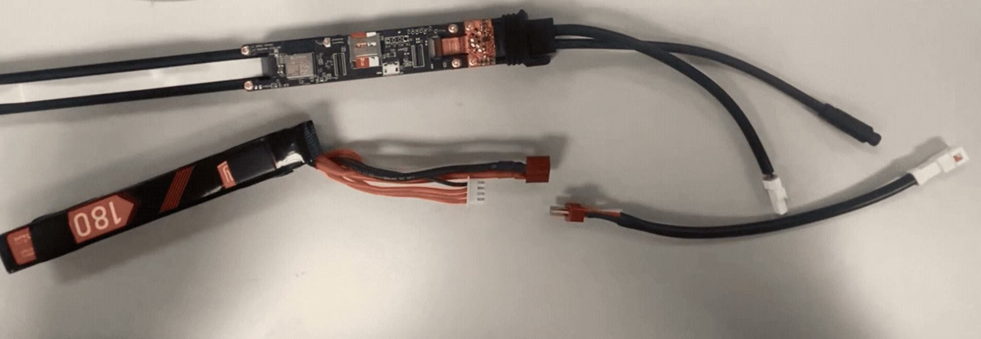
To connect the included 11.1 V, 1800 mAh 3S Li-Po battery pack:
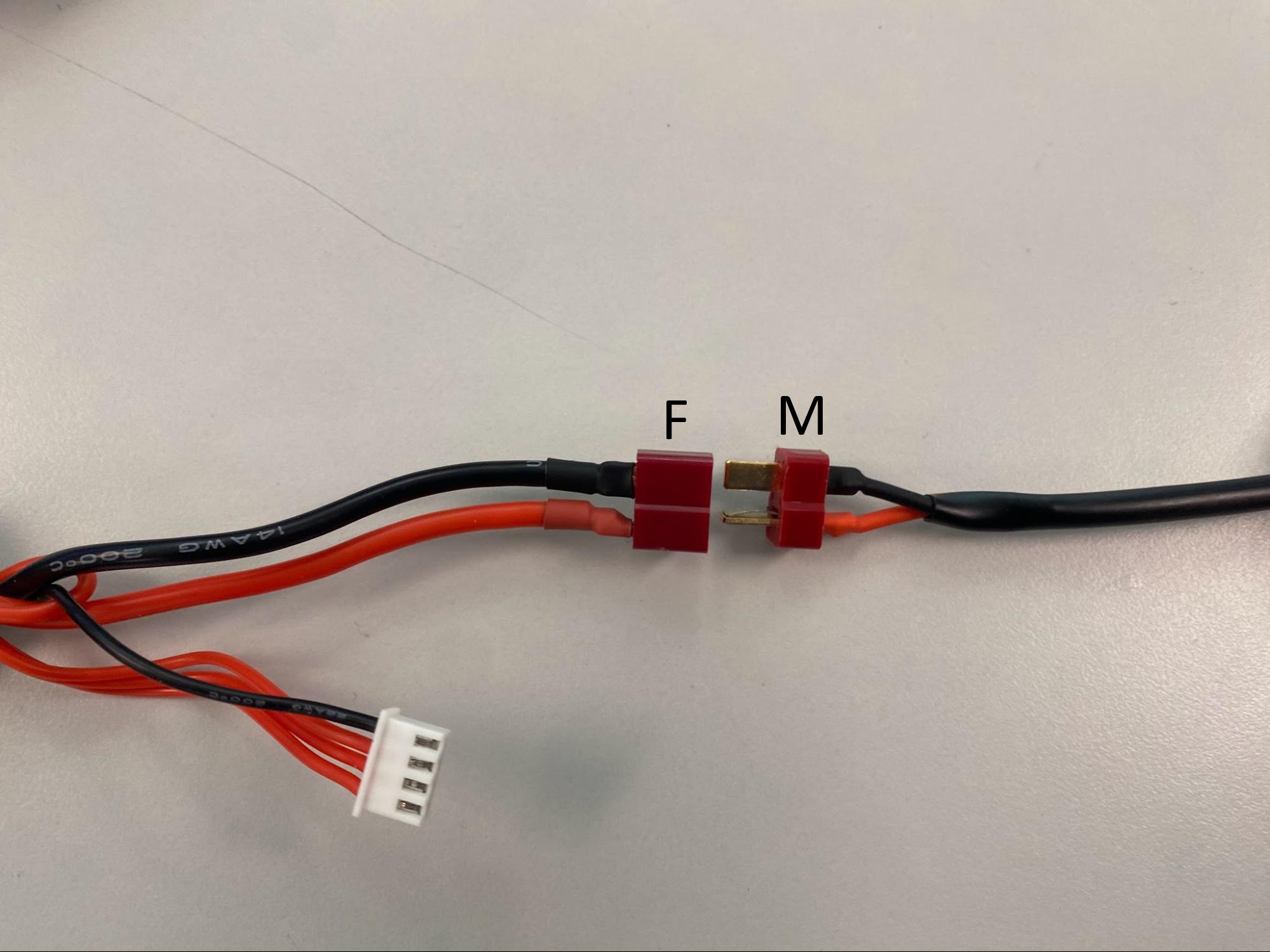
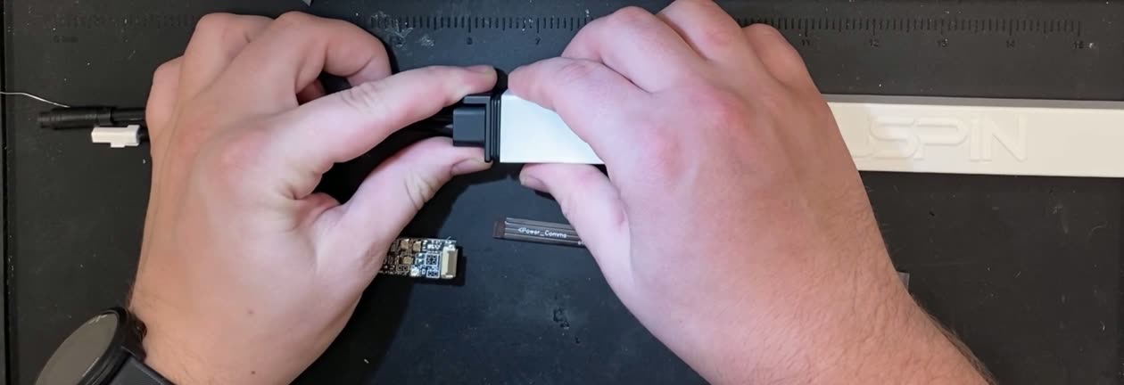
Confirm that the red battery adapter is fully seated and secured.
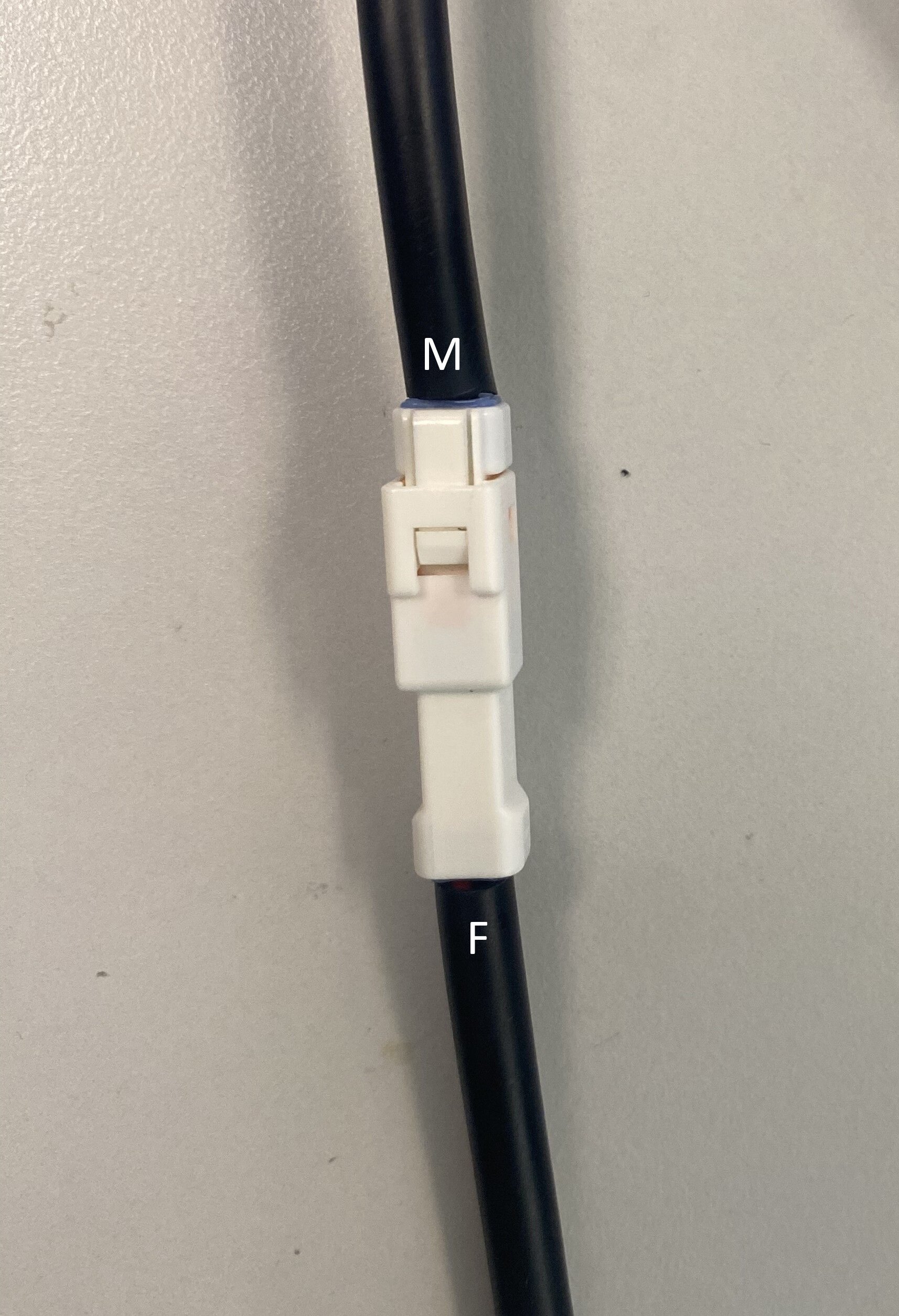
Align the white male Magpie connector (M) with the female battery connector (F).
Push the connectors together firmly until they click into place.
Left: the battery adapter, disconnected — the female (F) and male (M) connector ends. Right: the Magpie connected to the battery.
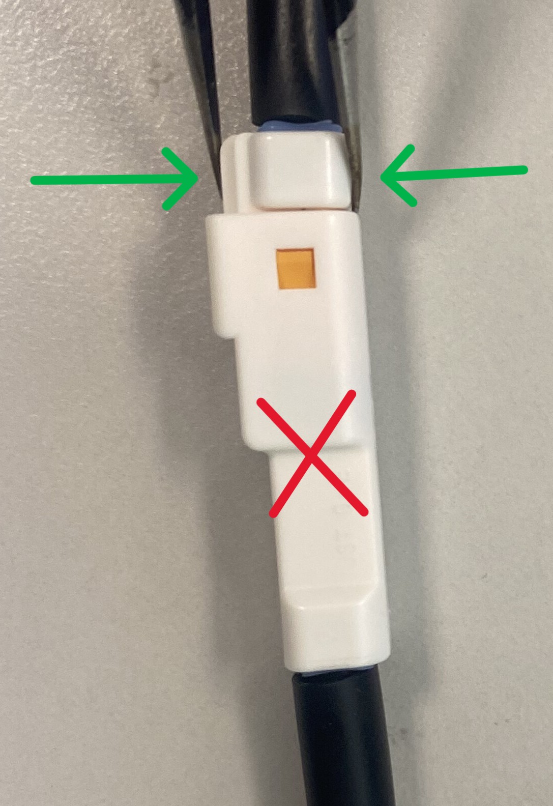
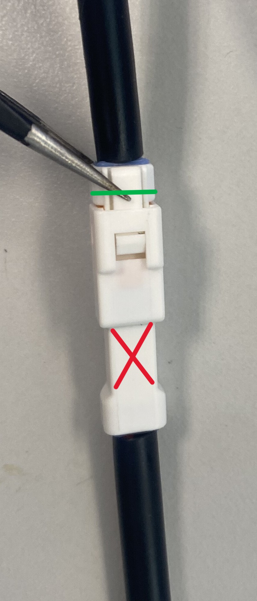
To disconnect the battery:
Locate the connector closest to the Magpie sled (M).
Squeeze the locking tab down against the connector body to release it.
Pull the battery-side connector (F) straight out; it should release with minimal force.
Battery release. Release the connector closest to the Magpie sled (green); do not pull on the battery connector (red). Full Li-Po battery connect and disconnect sequence. Watch in the online guide →
9.2 Removing the Magpie Shell
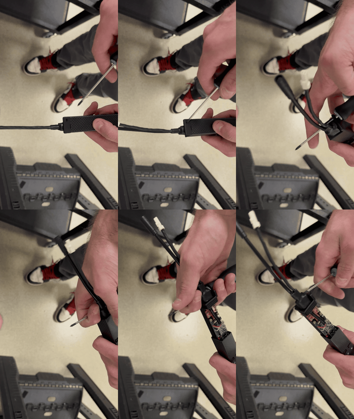
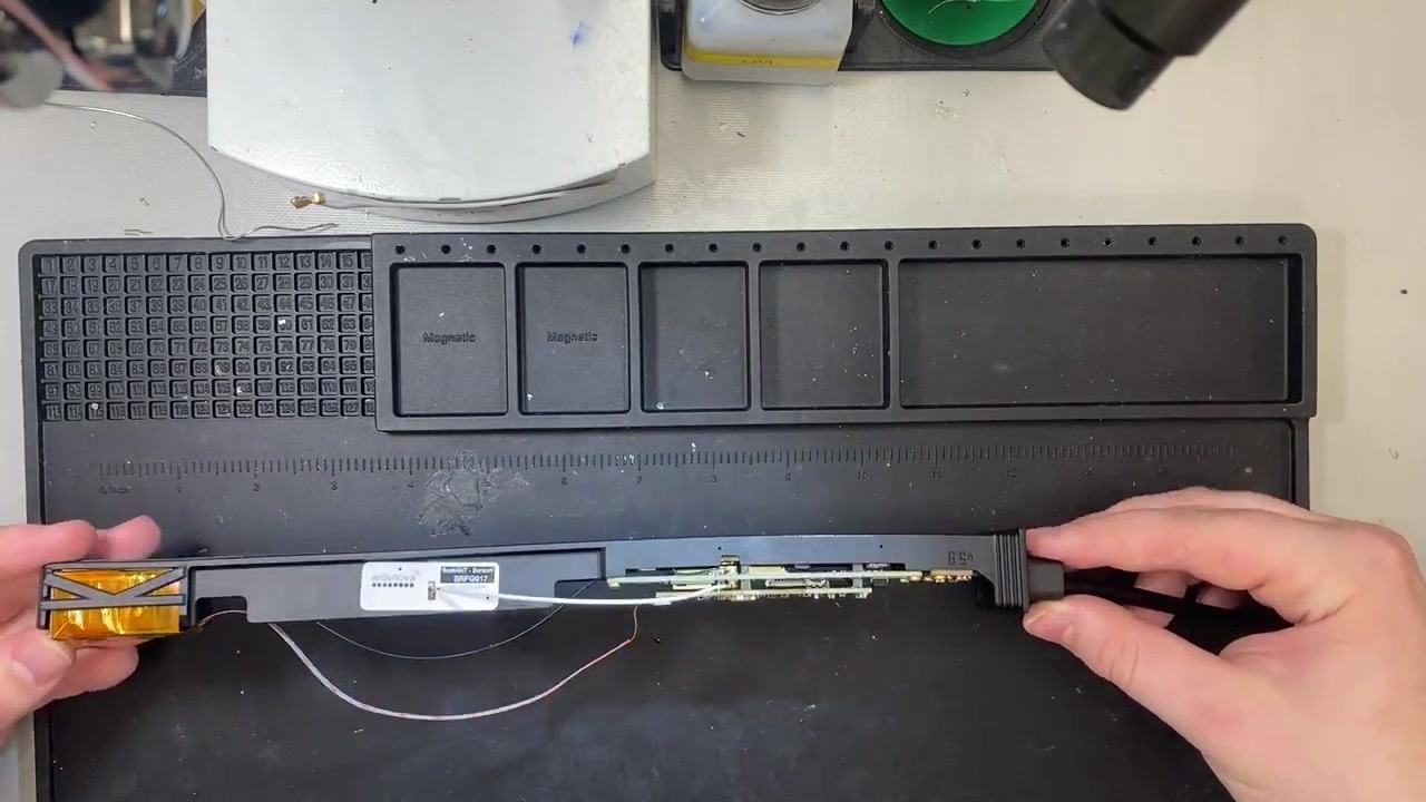
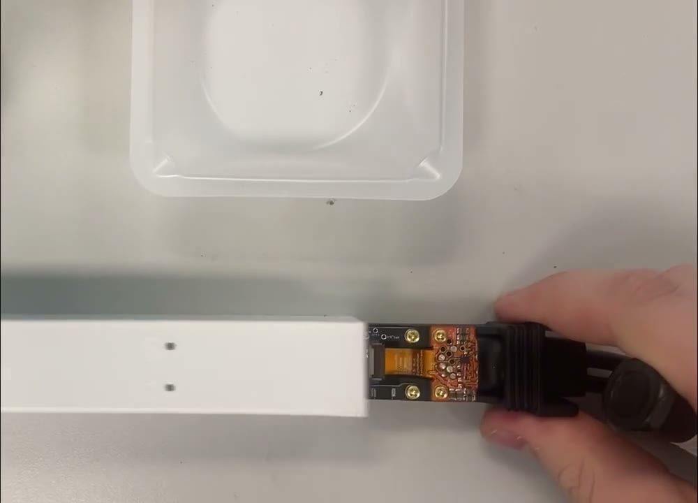
Removing the Magpie’s outer shell is necessary for several tasks, including removing the SD card, updating firmware, and accessing the internal boards. To remove the shell, insert a screwdriver through the provided hole and use it as a handle to pull the sled free of the shell.
Removing the Magpie shell. (Animated.)
9.3 Removing the SD Card
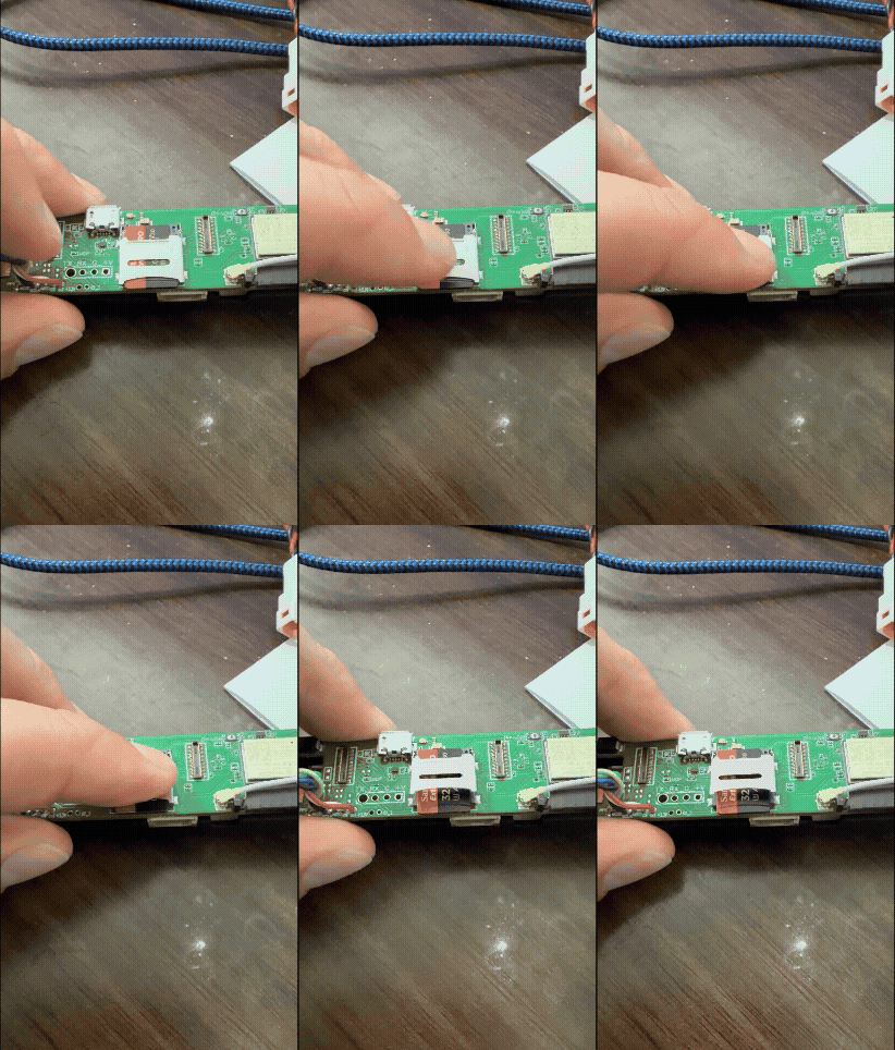
The Magpie logs all recorded data to the SD card; remove it to read your data directly on a computer or to swap in a fresh card. First remove the outer shell (see Figure), then locate the SD card slot on the MiniACB. To release the SD card holder, gently push it away from the edge of the Magpie; the holder will pop up.
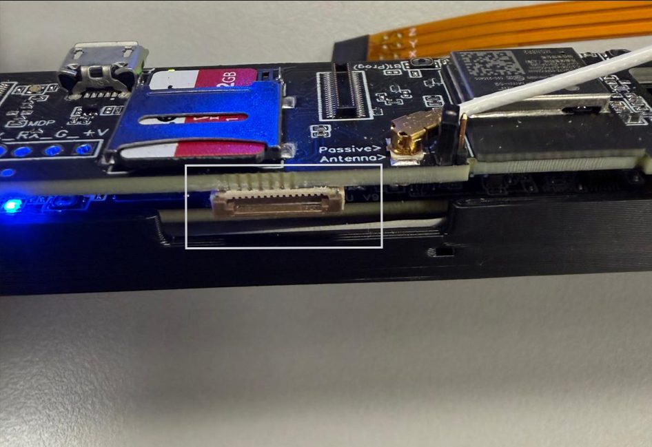
A standard QuSpin Comms board (SCB) plugs into the flex-cable connector on the side of the MiniACB for a
direct serial link to the sensor — useful for updating sensor firmware.
Connecting a standard Comms board (SCB) to the MiniACB flex-cable connector. Watch in the online guide → Flex-cable connector on the side of the
MiniACB board (white highlight).
Remove the Magpie shell and locate the flex-cable connector on the side of the MiniACB board, pictured above.
Connect the SCB via flex cable to the MiniACB, then power the SCB with a data micro-USB cable.
Open the COM port in the QTFM2 UI or any serial monitor.
Note For the fastest speed (to maximize RAM) you can enter
serial mode — the serial port must be set
to external by sending the following strings in order: [serial port external],[reboot]
,[serial on]. See the Magpie Command Guide → Serial Streaming
Mode for command reference.
As an alternative to the battery and sync cables, you can also power and communicate with the Magpie
through a Comms board over a single micro-USB cable — see Hardwiring Magpie inputs with a standard comms board.
10
Magpie Assembly
If you need to assemble your Magpie, follow the steps below.
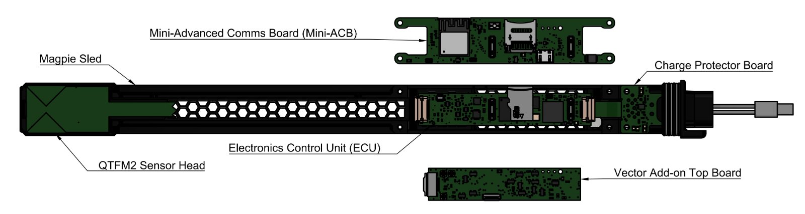
The Magpie is built around a central sled that carries its electronics and sensor. The labeled breakout below identifies the components referred to throughout this chapter.
Magpie component breakout: the sled and QTFM2 sensor head along the body, with the Mini-Advanced Comms Board (MiniACB), Electronics Control Unit (ECU), charge protector board, and Vector add-on top board. Magpie assembly walkthrough. Watch in the online guide →
Procedure
Lay out the components, tools, and hardware:
Category
Items
Magpie Components
Magpie sled
Charge protector board with input cables
ECU
External GPS adapter cable (black)
Internal GPS antenna with cable (white)
MiniACB
QTFM2 sensor head
Magpie outer shell
Vector Add-on Components (optional)
Vector coil add-on top board
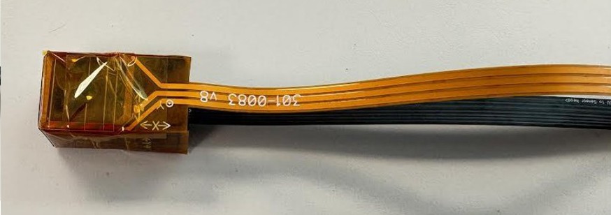
Vector coil flexible printed circuit (FPC)
Tools and Hardware
Tweezers
Screwdriver
Double-sided tape
6 × M2-0.4×6 mm screws
Apply double-sided tape to the sled in the areas beneath the ECU and sensor head, but do not peel off the top layer yet.
Slide the input cables through the open end of the sled and fasten the charge protector board to it with two M2-0.4×6 mm screws. To install different cables, see Integrating Alternate Cables.
Connect the ECU to the charge protector board’s flex cable; it should sit on the taped area. Tuck the external GPS adapter cable (black) underneath the ECU. Refer to Figure for ECU orientation.
Connect the external GPS cable (black) to the UMCC port on the bottom of the MiniACB, then attach the MiniACB to the ECU.
Peel off the top layer of the ECU tape and press the ECU and MiniACB into place. Confirm that the mounting holes on the MiniACB align with the sled’s screw holes, then fasten the MiniACB with the remaining four screws.
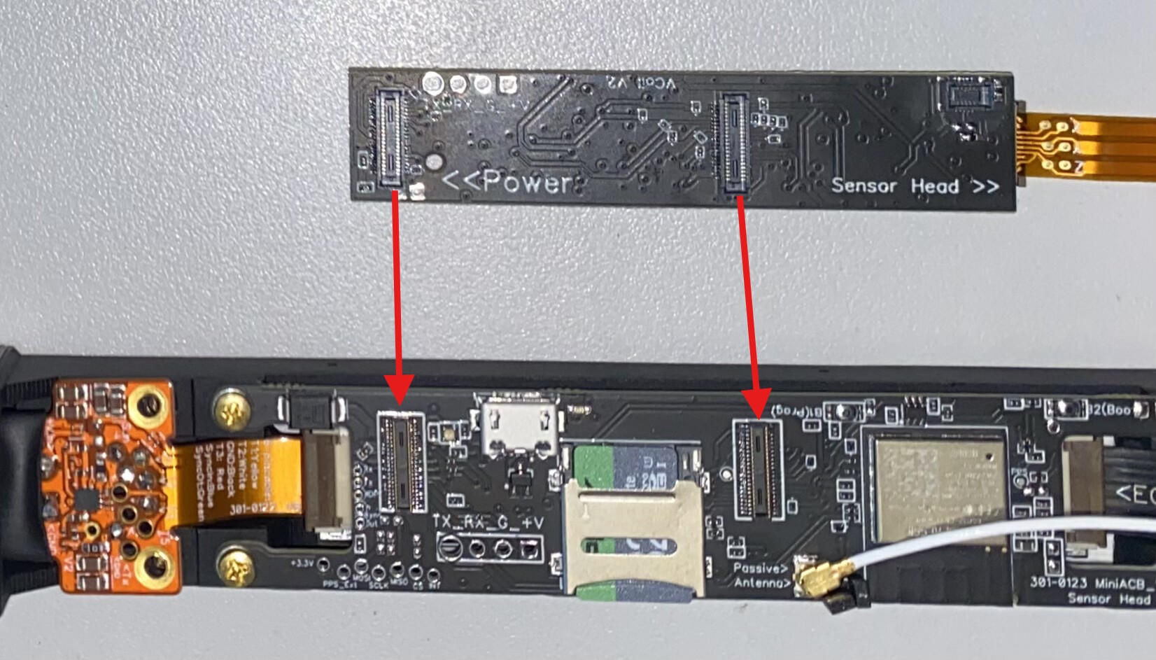
Connect the sensor head’s flex cable to the ECU. Connect the internal GPS antenna (white) to the MiniACB’s top UMCC connector.
Vector coil add-on If installed, attach the vector add-on board to the top of the MiniACB and connect the vector coil FPC to its flex port. See Vector Coil Installation below for more details.
Peel off the top layer of the sensor head tape and press the sensor head into place.
Slide the outer shell onto the sled.
Note To disassemble the Magpie, follow these steps in reverse.
Vector Coil Add-on Installation
The vector coil add-on adds three-axis (vector) magnetic-field readout on top of the Magpie’s scalar
QTFM2 sensor. On vector-equipped units the coil FPC's wrap around the sensor head and the vector electronics board
mounts on top of the MiniACB.
Power off the Magpie and remove the outer shell so the sensor and MiniACB are accessible. Remove the sensor from the sled.
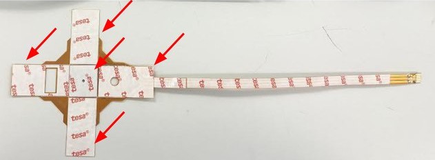
Take the vector coil flexible PCB and remove the adhesive backing from the five sections indicated.
Remove the adhesive backing from the five indicated sections of the vector coil flex-PCB.
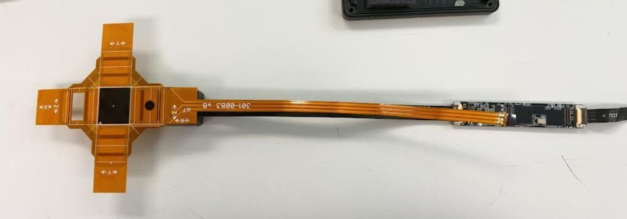
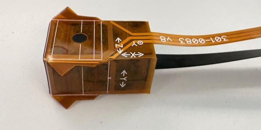
Align the vector coils from the top of the sensor, opposite the serial number. Wrap the coils around the sensor head and firmly press into place.
Align the coils with the flex-cable section on top of the sensor, then wrap them around the sensor head and rub to adhere.
Snap the vector top board onto the MiniACB, then attach the vector coil flex cable to the flex connector on the vector top board. Make sure the board seats fully and sits flush against the MiniACB.
Snap the vector top board onto the MiniACB, then attach the vector coil flex cable to the board’s flex connector.
Tape the folded coil edges down with Kapton tape so they do not catch on anything during use.
Fold the coil edges down and secure them with Kapton tape.
Return the sensor to the sled and slide it back into the outer shell.
Important It is crucial to calibrate newly installed
vector coils to enhance sensitivity and noise tolerance before collecting data. See Vector Coil Optimization for the full procedure.
11
6-Pin Breakout Cable
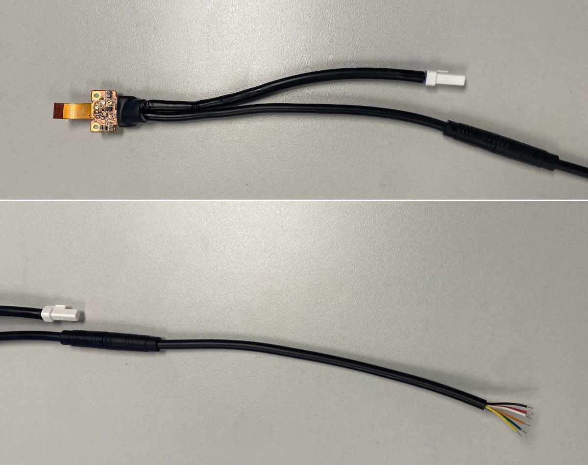
The 2-pin + 6-pin breakout board that ships with every Magpie carries battery power on its 2-pin cable and exposes the sensor’s serial UART and synchronization lines on its 6-pin cable. It is the primary way to integrate Magpie into custom platforms, hard-mounted deployments, multi-sensor arrays with a shared 1 PPS, and any setup that needs a wired serial connection to the sensor (for example Ethernet streaming via the W5500 module, USB-UART data capture, or driving an External PPS Sync array).
Both cables use Julet M6 waterproof connectors. The 2-pin cable mates directly with the standard Magpie power cable’s opposite end; the 6-pin cable has six individually-colored conductors at its open end.
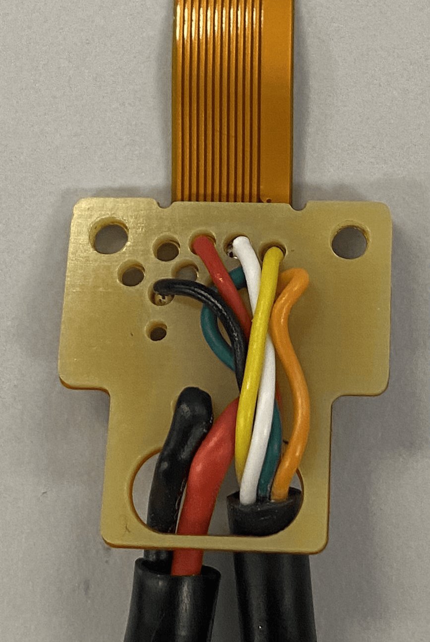
Magpie 6-pin breakout cable: the colored conductors at the open end. The colors and signal names match the table below.
Pin / Wire-color Map
Wire color (label)
Function
White (T2)
UART Rx — serial data into the Magpie (host TX connects here).
Red (T3)
UART Tx — serial data out of the Magpie (sensor data stream, status messages).
Black
GND — common ground reference. Must be tied to the host’s ground for any UART or Sync connection.
Orange*
Sync_Input — external 1 PPS or master clock input. Drive with a 0–3.3 V edge to feed an External PPS sync source or a wired master clock.
Green
Sync_Output — clock / sync pulse out of the Magpie. Use for daisy-chaining a slave sensor in wired Master/Slave mode, or for external monitoring.
Yellow (T1)
Unused (reserved). Leave disconnected.
* On older input cables the Sync_input conductor was blue rather than orange.
Notes on the Signal Lines
UART logic levels are 0–3.3 V (3.3 V CMOS) and the default Magpie baud rate is 921600 bps, 8N1. When wiring to a host or USB-UART adapter, connect the host’s TX to White and its RX to Red, then tie Black to the host’s ground. To stream Magpie data directly out of this UART port and send commands over the external UART, send [serial port external].
Sync_Input and Sync_Output are 3.3 V logic signals. For wired Master/Slave sync, run a wire from the master’s Sync_Output (Green) to the slave’s Sync_Input (Orange) and tie the two Blacks together. For External PPS Sync, fan the same external 1 PPS source (typically a 0–3.3 V GPS PPS line) to every sensor’s Sync_Input (Orange) and tie all the Blacks together. See Time Synchronization for the full setup of each method.
If you damage the connector or open end of the cable, the spare female 6-pin Julet M6 connector included with every Magpie shipment can be soldered or crimped on to rebuild the cable. The 2-pin spare connector serves the same purpose for the power cable.
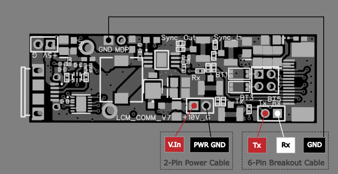
Hardwiring Magpie Inputs with a Standard Comms Board (SCB)
As an alternative to the two cables, the spare 2-pin power and 6-pin breakout
connectors can be wired to a standard QuSpin Comms board (SCB). A single data-capable micro-USB cable
then supplies power to both the Comms board and the Magpie, and provides the external serial link.
This configuration is recommended when battery operation of the Magpie is not needed. Wire the
connectors to the labeled Comms-board pads as shown, then set the serial port to external using
[serial port external]. See the Magpie Command Guide
for the full command reference.
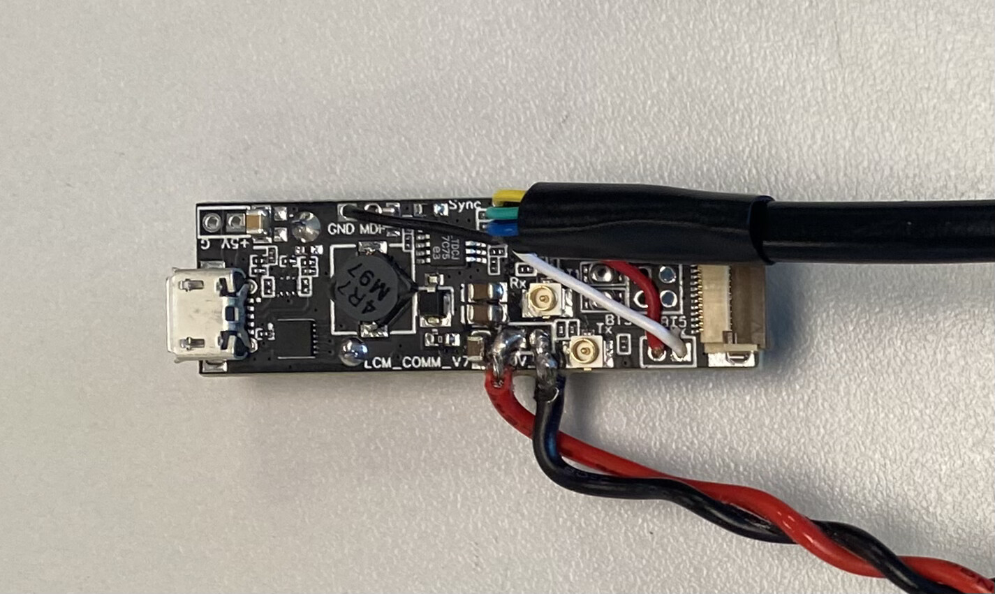
Wiring the spare 2-pin power cable (V.In, PWR GND) and 6-pin breakout cable (Tx, Rx, GND) to a standard Comms board for USB power and the external serial link.
Standard Comms Board with power cable and serial link modifications.
Notes
If only power is required and the data connection will be handled via Wi-Fi or Bluetooth,
simply wire the 2-Pin power cable — leave Rx and Tx disconnected.
We recommend wrapping the floating wires (orange/blue, green, yellow) with electrical tape.
12
Integrating Alternate Cables
WarningThis procedure involves soldering. Proceed only if you are comfortable with electronics rework. Improper reassembly may damage the Magpie.
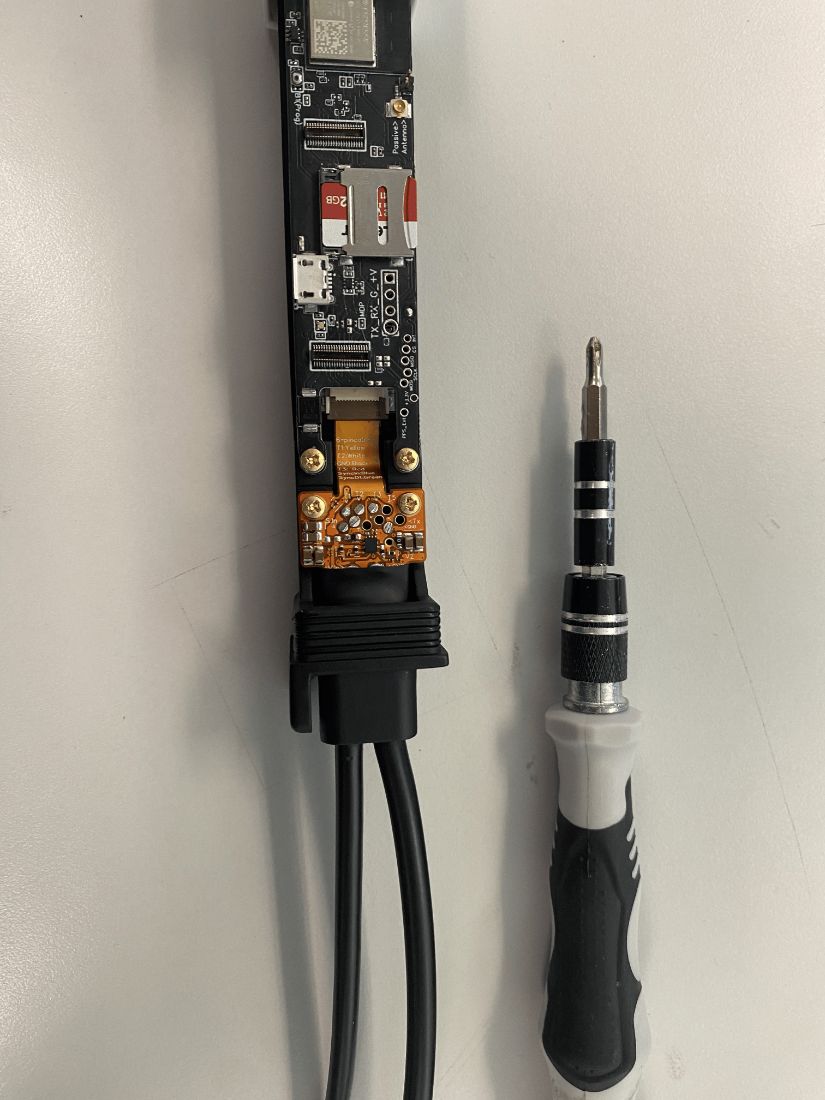
Remove the two M2-0.4×6 mm screws nearest the connector cables (highlighted in Figure).
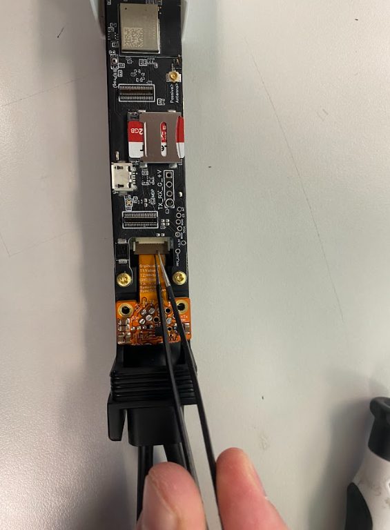
Flip the hinged flex-cable connector upward and disconnect the flex cable (Figure).
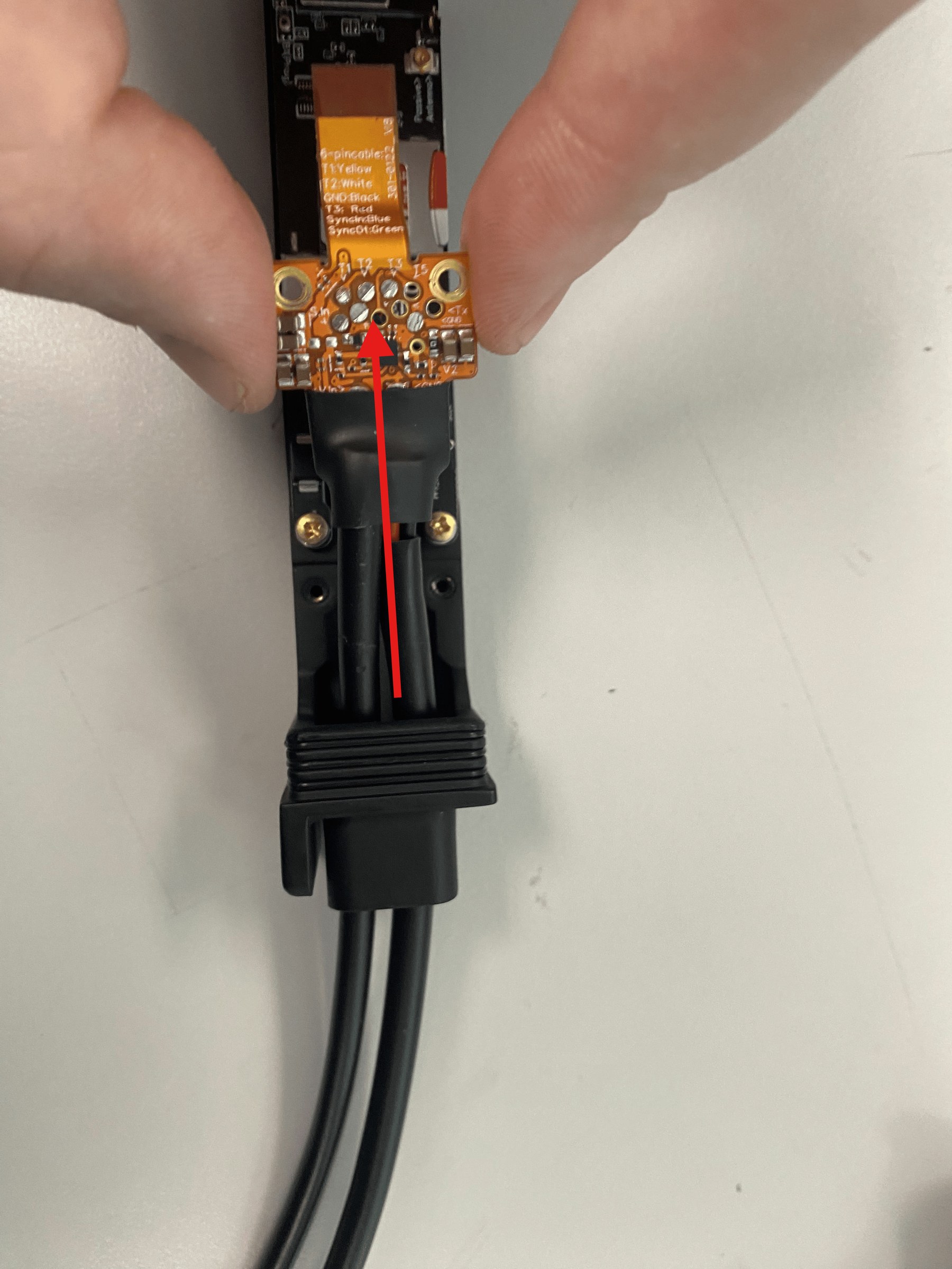
Remove the charge protector board and input cables from the Magpie sled to expose the underlying wires (Figure). Feed the two input ports through the Magpie sled one at a time.
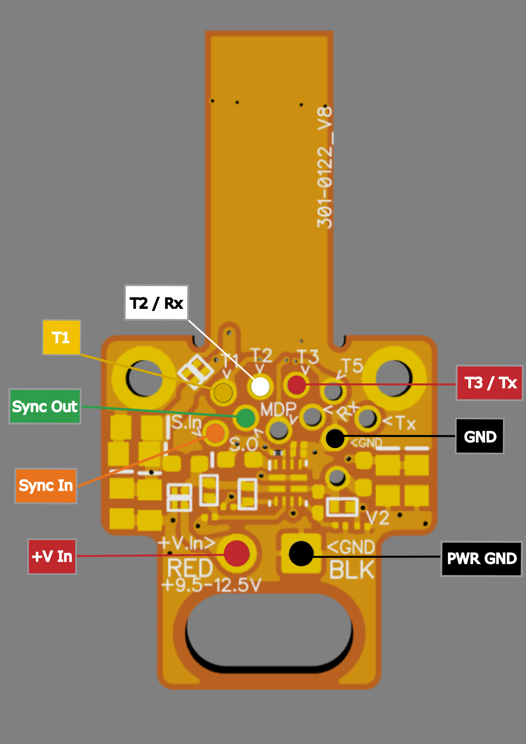
Use the wire-color reference below to match each wire to its pad.
Desolder the existing cables and solder your replacement cables to the corresponding pads.
Apply and heat 5/8″ heatshrink around your replacement input cables.
Left: Magpie with the case removed; the screws to remove are highlighted. Right: the hinged flex-cable connector to disconnect, shown with tweezers.
Left: removing the charge protector board. Right: the exposed input-cable wiring.
Note To reassemble, reverse steps 1–4 — reattach the charge protector board, reconnect and close the flex-cable latch, reinstall the two screws, and close the outer shell.
Wire-color Reference
Sensor & sync cable (6-pin)
Wire color
Pad
Function
Yellow
T1
Reserved
White
T2
UART Rx
Black
GND
Ground
Red
T3
UART Tx
Orange*
S.In
Sync input
Green
S.O
Sync output
Power cord (2-wire)
Wire color
Port
Function
Red
V.In
+9.5–12.5 V supply
Black
GND
Ground
Wire colors are consistent across units; the power cord connects to the V.in (RED) and GND (BLK) ports at the base of the board. * On older input cables the Sync input conductor was blue rather than orange.
Alternate-cable input pinout for the Magpie MiniACB. Solder UART Rx to T2 (White) and Tx to T3 (Red).
Note The standalone Rx and Tx pads are not connected to T2/T3 — they are a separate UART from the MiniACB’s microcontroller. For the sensor’s serial connection, use T2 (UART Rx, White) and T3 (UART Tx, Red), and leave the standalone Rx/Tx pads unconnected.
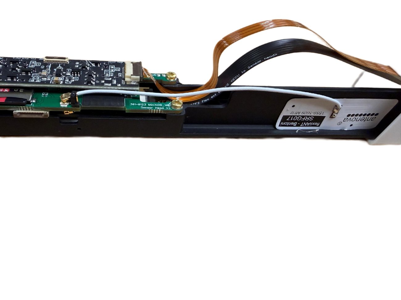
Magpie with housing removed, showing the internal pre-connected GPS antenna.
Magpie ships with the internal passive flex GPS antenna pre-connected as shown above. For most users and deployments, an external GPS antenna is not required. When the unit is operated outdoors with a clear view of the sky, it will begin acquiring satellites and should achieve GPS lock automatically.
Note The internal GPS antenna is intended for use with the standard plastic Magpie shell. Carbon-fiber enclosures can attenuate GPS signals, which may prevent reliable satellite acquisition. If you are using a carbon-fiber shell, QuSpin recommends installing an external GPS antenna.
13.2 Connecting an “Active” External Antenna
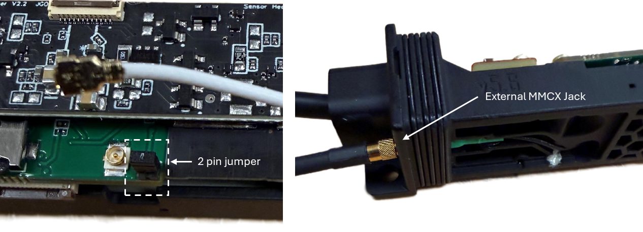
To use an active external GPS antenna — such as when operating in environments with limited sky view, when the internal antenna cannot achieve reliable lock, or when using a carbon-fiber shell — you can switch Magpie from its internal passive (flex) antenna to an external active antenna connection. Magpie ships with the external adapter cable disconnected and taped to the sled; leaving the cable plugged in alongside the internal antenna creates RF interference that significantly extends GPS lock time. To switch to the external configuration, open the Magpie shell, disconnect the internal passive GPS flex antenna, retrieve the external adapter cable from where it is taped to the sled, and connect the cable’s UFL plug to the GPS receiver (either of the two GPS receiver ports). Then install the provided 2-pin jumper to enable the active-antenna power path.
Reinstall the plastic or carbon-fiber shell onto the Magpie sled, and connect your external antenna to the MMCX (female) jack on the outside of the Magpie.
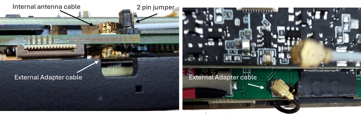
Left: close-up of the Magpie internal antenna connection (shown disconnected) and 2-pin jumper configured for an active external antenna. Right: close-up of the external MMCX jack with the external antenna attached.
ImportantIn this configuration the external antenna must be an active GPS antenna (i.e. one that includes a built-in low-noise amplifier). Most standalone external GPS antennas are active, while flex-style antennas are typically passive. QuSpin recommends external antenna part AN-GPS-A001-MMCX.
13.3 Connecting a “Passive” External Antenna
If you want to use your own passive external GPS antenna (typically a flex-style antenna), Magpie can route the GPS signal to the external MMCX port without enabling active-antenna power. Open the Magpie shell and disconnect the internal passive (flex) GPS antenna. Then remove the 2-pin jumper (leave it disconnected). Next, locate the external adapter cable on the bottom side of the PCB, unplug it, and reconnect it to the top-side UMCC connector. Reinstall the shell and connect your passive antenna to the external MMCX (female) jack on the outside of the Magpie.
Left: side view of the Magpie showing the top-side internal antenna cable and 2-pin jumper (both disconnected for a passive antenna), and the bottom-side external adapter cable. Right: top-down view with the 2-pin jumper removed and the external adapter cable connected to the top-side antenna jack.
This setup differs from the active configuration in one key way: a passive antenna does not include an amplifier and does not require power from Magpie, so the jumper must be removed and the signal routed through the UMCC connection path. For best results, mount the passive antenna on a non-conductive, rigid surface with a clear view of the sky. If you mount the antenna on the outside of a carbon-fiber shell, place several layers of non-conductive tape between the shell and the antenna to help reduce signal attenuation.
Part IV
Reference
14 Technical Specifications
15 Magpie Command Guide
16 Sensor Command Reference
17 LED Codes (Logger + Sensor)
18 Status Message Reference
14
Technical Specifications
14.1 Physical & Electrical
Parameter
Specification
Dimensions
290 mm × 25 mm × 25 mm
Weight
< 102 g (119 g with vector add-on), not including batteries
Operating Voltage
+9.0–13.9 VDC (any 11.1 V LiPo; non-magnetic 3S LiPo recommended)
Average Power Consumption
4 W at 11 V (typ.)
Peak Power Consumption
5.5 W at 11 V (peak)
Construction
White plastic casing (default); carbon-fiber casing available as an upgrade
Magpie’s MiniACB logger and Windows user interface accept configuration and control commands using a simple bracketed protocol. Each command must be sent enclosed in square brackets ([ … ]). Main command keywords are case-insensitive (for example, [PTP ON] and [ptp on] perform the same action), but command arguments — such as filenames — may be case-sensitive and should be entered exactly as intended.
15.1 General System Status
Command
Description
[id]
Identity: prints the Logger Serial Number, Bluetooth Name, and Wi-Fi SSID, then dumps the full saved-preferences block.
[test]
System Status: prints firmware version, bytes written, buffer lengths, overflow counters, and sync timestamps.
[bv] / [battery]
Battery Check: reads and prints the current battery voltage (to 3 decimal places).
[reboot]
System Reset: schedules a safe logger reboot (waits 1 second before restarting).
[update]
Firmware Update: schedules a firmware update from miniacb_firmware.bin on the SD card and reboots.
[refresh_sn]
Sync Serial Number: queries the connected sensor for its serial number and updates the logger’s configuration to match.
[set_v_offset X.X]
Calibrate Battery: sets the voltage offset for battery reading. Range 0.0 to 3.0 V. Example: [set_v_offset 0.5]
15.2 Data Logging Control
Command
Description
[start save]
Start Logging: manually opens a file and begins saving data.
[end save]
Stop Logging: stops saving data and closes the current file safely.
[auto log on]
Enable Auto-Log: automatically start logging immediately on boot (saved to memory).
[auto log off]
Disable Auto-Log: disables automatic logging on boot.
[auto log status]
Check Auto-Log: prints whether auto-logging is currently ON or OFF.
[max_size N]
Set File Limit: sets the maximum file size in MB. Example: [max_size 500]
15.3 PTP Time Synchronization
Command
Description
[ptp on]
Enable PTP Live: immediately enables PTP sync, starts the Ethernet stream, and sets streaming active.
Check PTP: prints current PTP status and whether it is enabled at boot.
[ptp boot on]
Enable PTP Boot: configures device to enable PTP automatically on the next boot (saved to prefs).
[ptp boot off]
Disable PTP Boot: disables PTP auto-start on boot.
15.4 Serial Streaming Mode
Command
Description
[serial on]
High-Speed Serial: immediately kills Bluetooth and enables high-speed data streaming over USB Serial.
[serial off]
Stop Serial Stream: stops the high-speed serial data stream.
[serial boot on]
Enable Serial Boot: boot into Serial-Only mode next time (saved to prefs).
[serial boot off]
Disable Serial Boot: disables Serial-Only mode on boot.
[serial boot status]
Check Serial Mode: prints current live status and saved boot preference.
15.5 Connectivity & Modes
Command
Description
[mode]
Check Mode: displays the current operating mode (WiFi/Bluetooth/Manual), ASPN status, and whether a file is open.
[mode ethernet]
Set Boot Mode (Ethernet): boot into Ethernet mode next time. Requires a reboot to take effect.
[mode log]
Set Boot Mode (Log): boot into standard Logger mode next time. Requires a reboot.
[eth on]
Ethernet On (Live): immediately initializes the W5500 Ethernet driver, HTTP server, and UDP streams without rebooting.
[eth off]
Ethernet Off (Live): immediately disables the Ethernet hardware.
[serial port internal]
Routes the sensor serial UART to the internal USB port. Required before enabling Ethernet (GPIO IO20 is shared with the W5500 SPI bus).
[serial port external]
Routes the sensor UART to the external serial port (default factory state). Use when not running Ethernet so the 6-pin breakout cable’s UART lines are active.
15.6 Advanced Sensor Processing (ASPN)
Command
Description
[aspn on]
Enable ASPN mode (saved to memory).
[aspn off]
Disable ASPN mode (saved to memory).
[aspn status]
Prints whether ASPN mode is currently active.
[gps_format]
Shows the current ASPN GPS message format.
[gps_format 3d]
Geodetic3D output (ICD 1001.3) — the default. WGS-84 latitude and longitude in radians, altitude in meters (ellipsoid height), and a 3×3 covariance about North, East, Down.
[gps_format 2d]
Legacy Geodetic2D output (ICD 1001.2): latitude and longitude only, with a 2×2 NE covariance. For subscribers still bound to the old message format.
Note Switching formats automatically updates the GPS device-ID URI icd_num (1001.3 or 1001.2) when the URI is still in the standard auto-generated form; custom URIs are left unchanged. On the first boot after upgrading to MiniACB V5.12, a saved standard-form GPS URI is migrated automatically to match the active format — no action is required.
15.7 Heartbeat Settings
Command
Description
[hb on]
Enable Heartbeat: turns on the periodic heartbeat message.
[hb off]
Disable Heartbeat: turns off the heartbeat message.
[hb interval X]
Set Interval in seconds (or minutes with ‘m’). Example: [hb interval 30] or [hb interval 5m]
[hb status]
Check Heartbeat: prints the current enabled status and interval.
15.8 SD Card Management
Note These commands often require a multi-line input method, or they read the very next line sent after the command.
Command
Description
[list_sd_dir]
List Directory: lists files in a directory. Send the directory path (e.g. /) immediately after.
[create_sd_dir]
Make Directory: creates a new folder on the SD card. Send the path immediately after.
[delete_sd_filename]
Delete File: deletes a specific file. Send the filename immediately after.
[get_sd_card_info]
Card Info: prints SD card type (SDHC/SDXC) and total/used capacity.
15.9 Debug & Tweak Tools
Command
Description
[bt++]
Decrease Resolution: increases appendEveryN. Skips more data points in the stream (subsampling).
[bt--]
Increase Resolution: decreases appendEveryN. Includes more data points in the stream.
15.10 GPS
Command
Description
[gps on] / [gps off]
Show or suppress GPS NMEA / fix lines in the output stream. Useful indoors or in GPS-denied environments.
[gps status]
Reports current fix type, satellite count, HDOP, and signal quality from the onboard receiver.
[gps timing]
Prints timing-jitter diagnostics for the GPS pulse-per-second (PPS) input. Used to verify PPS edge alignment.
15.11 Wireless GPS Sync (Magpie → Sensor)
Note Requires sensor firmware V1_43+ and FPGA bitstream V5.05+; MiniACB V5.10+ refuses engagement with a clear error if either gate isn’t met.
Command
Description
[gps_sync_auto on/off]
Turnkey mode — the Magpie waits for a GPS fix, waits for the sensor to finish autostart, then automatically sends sensor commands 113, 206, 209, and 230 to engage wireless sync. “Off” disables both the auto-arm state machine and UTC frame forwarding.
[gps_sync on/off]
Manual mode — the Magpie forwards the 11-byte UTC sync frame on every GNSS fix; you configure the sensor side yourself.
[gps_sync status]
Reports forwarding state, auto-arm state-machine position, sensor autostart-complete flag, sensor cell-locked flag, and the parsed sensor firmware / FPGA versions.
15.12 Networking (Ethernet and TCPService)
Note Requires the W5500 Ethernet breakout board (sold separately). See Ethernet Operation for first-time setup and packet formats.
Command
Description
[eth status]
Reports IP, subnet, gateway, link state, and connected client count.
[eth binary on/off]
Switch the Ethernet data stream between ASCII (default) and a compact binary packet format.
[eth ip <A.B.C.D>]
Set the Magpie’s static IP. Saved to NVS; reboot to apply. Default 192.168.10.2.
[eth subnet <A.B.C.D>]
Set the subnet mask. Saved to NVS; reboot to apply. Default 255.255.255.0.
[eth gateway <A.B.C.D>]
Set the gateway IP. Saved to NVS; reboot to apply.
[tcp_service ip/port]
Configure the LCM TCPService outbound publisher destination. Defaults to 192.168.10.1:7700.
[tcp_service status]
Reports the saved IP, saved port, and current TCPService connection state.
15.13 LCM Channels and ASPN Device IDs
Override the published-channel names and ASPN device-ID URIs for the five logical streams (total_field, threeaxis, imu_vmag, inertial, gps). Defaults are MAGPIE_* channel names and sdm://magpie/<SN>/<icd>/<topic> URIs.
Command
Description
[channel status]
Lists current channel names for all five streams.
[channel reset]
Restores all five channel names to the MAGPIE_* defaults.
Restores device IDs to the standard sdm:// defaults.
[device_id <key> <uri>]
Override one device-ID URI. Same key set as [channel].
15.14 Diagnostics, Profile & Miscellaneous
Command
Description
[hw_rev] / [hw_rev status]
Prints the configured hardware revision and the active pin map. Informational and safe.
[hw_rev v7] / [hw_rev v8] / [hw_rev clear]
Overrides the stored hardware revision. The SPI bus pins are identical on V7 and V8 hardware; this setting only controls whether the V8-specific USB-detect feature is active. See the caution below.
[print on] / [print off]
Enable or disable verbose console printing on the Magpie’s terminal.
[factory reset]
Restore every saved preference to its compiled default. Clears the cached serial number, custom Ethernet IPs, channel names, device IDs, and feature toggles.
[set_sd_filename <name>]
Override the base filename used for SD-card saves. Saved to non-volatile memory. [refresh_sn] resets the base name back to the sensor-serial form.
[ptp pps on/off/status]
Enable, disable, or query PTP-PPS discipline. When on, the PTP offset estimator is corrected once per second by the GPS PPS edge for sub-microsecond stability.
[serial port status]
Reports whether the external serial port (IO20/IO38) or the internal USB serial is currently active.
[bt status]
Reports Bluetooth backend, advertised name, and connection state.
[sm_inc]
Increment the sensor’s slave-mode index (used in multi-sensor master/slave wired-sync arrays). Companion to [sm].
[set_leap_offset <seconds>]
Manually adjust the GPS→UTC leap-second offset. Used only when the receiver’s broadcast leap-second value is wrong or missing.
CautionOnly change the [hw_rev] setting if directed by QuSpin support. On V7 hardware the V8 setting can cause the unit to switch serial modes unpredictably at boot; correct it with [hw_rev v7] followed by a reboot.
15.15 Passthrough Commands
The Magpie’s command parser recognizes three distinct command forms and routes each to a different destination.
Form
Goes to
What it is
Reference
Bracketed [command]
Magpie / MiniACB logger
Logger commands — the ones documented above in this chapter. The brackets are consumed by the logger and are never forwarded to the sensor.
This Chapter
Tilde-Wrapped ~command~
QTFM2 Sensor
Utility commands (e.g. ~Start~, ~Stop~, ~report~) and configuration-profile loads (e.g. ~Vector_Survey_Pro~).
The configuration and profile commands write to non-volatile memory, so those changes persist across sensor reboots.
Single-character ASCII commands (e.g. s for startup settings, e for sensor reboot) and decimal command numbers (e.g. 34 for a short status dump). These act on the current session only.
ImportantAll QTM2 sensor commands are case-sensitive.
16
Sensor Command Reference
Magpie is built around the QuSpin QTFM Gen-2 sensor and supports the full QTFM Gen-2 serial command set for configuring sensor behavior, selecting operating modes, managing startup behavior, enabling filters, toggling vector or scalar mode, and accessing diagnostic information. The single-character ASCII commands can be sent through the all-in-one QuSpin Windows software, the MiniACB browser terminal, the Android app, or any standard serial terminal. Sensor commands are forwarded to the sensor when left bare (single characters) or wrapped in tildes (strings) — for example, a bare s prints the sensor’s startup settings, and ~Start~ enables autostart on power-up (see Passthrough Commands in the Magpie Command Guide). For the complete and most up-to-date sensor command reference, see the QTFM Gen-2 Quick Reference (every command in one grouped table) and the QTFM2 Sensor Profile Configuration guide (built-in profiles and custom slots) on the QuSpin website.
17
LED Codes (Logger + Sensor)
Magpie sled showing the logger “L” and sensor “S” LED indicators.
The Logger and Sensor LEDs are found on the Magpie sled, marked “L” and “S” respectively. The Sensor LED communicates magnetic data quality (idle, valid measurements, or conditions such as high gradients or dead zones). The Logger LED reflects recording status and GNSS lock.
Quick action guide (logger “L” LED)
Blinking red → fault detected and not logging. Check microSD card, battery voltage, and restart.
Yellow / blue / green states → Magpie is waiting on GNSS lock and/or magnetic data. Start logging once your required signals are present.
White (blinking/solid) → GNSS lock and magnetic data present. Recommended state before a critical recording.
17.1 Logger LED Codes
LED indicator
Status description
Blinking Red
Error condition (SD card missing, low battery, etc.). Data not logging.
Waiting for both GNSS and magnetic data. Not logging.
Yellow
Waiting for both GNSS and magnetic data. Actively logging.
Blinking Blue
Magnetic data detected, GNSS not locked. Not logging.
Blue
Magnetic data detected, GNSS not locked. Actively logging.
Blinking Green
GNSS locked, magnetic data not detected. Not logging.
Green
GNSS locked, magnetic data not detected. Actively logging.
Blinking White
Both magnetic data and GNSS lock obtained. Not logging.
White
Both magnetic data and GNSS lock obtained. Actively logging.
17.2 Sensor LED Codes
LED indicator
Status description
Blinking Red
Idle (flashes every 1 s in Master mode and every 0.5 s in Slave mode).
Yellow
AutoStart in progress.
Blue
Transmitting valid magnetic field data.
Red
Bad data (high gradient or in a dead zone).
Solid White (new)
GPS wireless-sync indicator (default). The sensor is in GPS Sync mode (cmd 113), receiving valid UTC frames from a Magpie, and the current measurement is good. Held at constant brightness so it contributes no per-second magnetic signature. Bad data still overrides as solid red.
Per-Second Rainbow (optional)
Troubleshooting view for GPS wireless sync (off by default). Enabled with sensor command 235. Steps through Yellow → Green → Cyan → Blue → Purple, one color per UTC second, in lockstep across all synced sensors. Radiates a small 1 Hz magnetic signature, so use for troubleshooting rather than clean recording. Reverts to solid white on reboot.
18
Status Message Reference
The Magpie’s console emits one of three line types: status (prefixed with #), magnetometer data (prefixed with a microsecond timestamp and !), or GPS / IMU records (timestamp + , or other tag). Every status line is informational unless it starts with the word ERROR. WARNING lines are advisory. This section catalogs the messages an operator most commonly sees, grouped by category.
18.1 Boot and Initialization
Status lines you see immediately after the Magpie powers on. The boot banner ends with #Ready — once that prints, the Magpie is ready to take commands and stream data.
Message
Meaning
#Initializing...
First line on cold boot. The Magpie has started setup() and is bringing up peripherals.
#FW Version: MINI_ACB_V5.12
Reports the currently-running Magpie / MiniACB logger firmware version.
#HW: V7 (default; send [hw_rev v8] if this is a V8 board)
Reports the configured hardware revision. V7 is the default and the expected value on all current units; do not change it unless directed by QuSpin support.
#Reset reason: N (POR/BOR/EXT/WDT/SW)
The cause of the most recent reset, printed each boot: POR = power-on, BOR = brownout, EXT = external reset pin, WDT = watchdog, SW = software reboot. A PANIC value means the previous run ended in a firmware crash — save the log and send it to QuSpin support.
#GPIO ISR service installed at LEVEL3 (flash-safe)
The high-priority interrupt service for the sensor MDP pulse was registered at interrupt LEVEL3 and is flash-safe. Expected on every boot.
#SD try @20/10/4MHz
The SD init code probes successively slower SPI clocks. Ends in “#SD card initialized successfully”. Repeated failures mean the card is bad, badly seated, or absent.
#SD stream buffer in PSRAM
The SD writer stream-buffer was allocated in PSRAM (preferred). A fallback to internal heap or an allocation failure is a board fault and should be reported.
#SD writer / Stream drain task running
The two helper tasks that move data off the main loop are alive. Both are required for sustained streaming.
#Mode: log / #Mode: ethernet
Reports which boot mode the saved preference selected. Change with [mode ethernet] or [mode log] + [reboot].
#ASPN: off / on (LCM binary)
Reports whether ASPN output conversion is enabled. Toggle with [aspn on/off].
#AP IP address: 192.168.4.1
The Magpie’s soft-AP IP address (Wi-Fi mode). Browse to http://miniacb/ or this address.
#BT backend: …
The Bluetooth Classic backend was initialized and is advertising. The advertised name is “<serial> BT”.
#BT MAC (serial-derived): 02:51:XX:XX:XX:XX
Printed when Bluetooth starts. The unit’s Bluetooth address is derived from its serial number, so changing the serial number changes this address (see Troubleshooting for re-pairing steps).
#Ready
The Magpie has finished boot and is ready to take commands. Sensor status messages may follow, passed through unchanged.
18.2 Saving Data to the SD Card
Message
Meaning
#Saving Data
A new file was opened and the SD writer is appending data to it.
#Unique filename: …
The unique filename chosen for this save. If the cached serial is still T2M0-0000, run [refresh_sn] to fix it.
#File closed successfully (NNNN bytes)
The save closed cleanly and NNNN bytes were written.
#File closed
Companion line to the close message; the SD writer was released. Appears for every save.
#Max file size reached.
The save hit the [max_size N] cap and was closed automatically. In auto-log mode a new file opens right away.
#Auto-log: opening new file...
Auto-log re-opened a new file after a previous close.
18.3 Save WARNING Messages
Pre-flight and post-flight warnings designed to make silent-failure saves visible. These do NOT halt the save — they tell you the save will likely be empty or interrupted so you can act before too much data is lost.
Message
Meaning
#WARNING: sensor autostart not complete
Printed at [start save] when the sensor hasn’t signaled autostart-complete. If the S LED isn’t solid blue, abort and let the sensor finish initializing.
#WARNING: no recent mag-data pulses
MDP pulse activity has been silent. Either the sensor isn’t streaming or the cable is broken.
#WARNING: sensor restarted Ns ago
A sensor reboot was detected within the last 8 s. Wait for autostart to finish before starting the save.
#WARNING: serial number is the default fallback
The cached SN was never replaced. Files will be named T2M0-0000_Data*.txt. Run [refresh_sn].
#WARNING: file closed but ZERO bytes written
The save completed but no data was captured. The block below it lists common causes and the cold-boot recovery procedure.
#WARNING: sensor restarted during this save
Mid-save sensor reset detected. The file contains a sensor-boot banner mid-stream; data after the gap is from a re-initialized sensor.
18.4 Diagnostic Counters
Message
Meaning
bytes written… overflows… mag_sync… gps_sync
After every flush, a one-line summary of the last interval: bytes appended, last/longest UART line length, dropped frames (should stay 0), and sync-event counts. A growing overflows count means the SD card can’t keep up.
#MAG Flush: stale pulse(s) discarded
The MDP timestamp ring flushed pulses older than the aging threshold. A small number at startup is normal; a steady stream means misclassification — report to QuSpin.
#GPS Flush: Discarded NN pre-GNZDA pulses
Similar housekeeping (#MAG Flush) for the GPS path.
18.5 GPS, PTP, and Wireless Sync
Message
Meaning
#GPS fix: …
Current fix type from [gps status]: “GPS Fix”, “DGPS Fix”, “No Fix”, etc.
#GPS output: ON / OFF
Response to [gps on] / [gps off].
#GPS sync: OFF / ON / AUTO / stayed OFF
Status of the wireless GPS-sync subsystem. “stayed OFF (refused)” means the sensor-FW or FPGA gates blocked engagement; following lines explain which gate fired.
#1PPS edges seen / healthy
PPS edge counter and a health flag. Healthy means edges arrive at the expected ~1 Hz cadence.
#PTP synchronization enabled & Streaming started
PTP discipline came up. Verifies that [ptp on] took effect.
#[gps_sync auto-arm] …
Turnkey state-machine status lines: waiting for GPS fix, configuring the sensor (sending 113/206/209/230), sync live, or PARKED if the sensor/FPGA is too old.
#[auto-SN] serial is fallback…
The periodic SN-handshake retry fired; the Magpie queries the sensor and updates the cached serial if the answer is real.
18.6 Errors and Stop Conditions
Message
Meaning
#ERROR: No SD card detected
[start save] was issued but the slot is empty or the card failed. Insert / re-seat / replace the card.
#ERROR: Failed to open file for writing!
SD.open() returned a null handle. Usually a card-format or card-fault problem; try reformatting (FAT32 or exFAT).
#ERROR: File was not properly closed!
[end save] was issued but the file handle was already null. A prior error path left the writer in a bad state.
#No SD card
[get_sd_card_info] couldn’t identify a card. The Magpie then reboots in case the card was just re-inserted.
#Error: Profile command timed out
A tilde-wrapped profile command got no response from the sensor in the expected window.
#Invalid IP / subnet / gateway format
The saved value was not updated. Use e.g. eth ip 192.168.10.5.
#FW UPDATE FAIL: …
OTA update failed during [update]. Fall back to the USB UART flash path in Firmware Updates.
18.7 Sensor Passthrough Lines
When the Magpie is connected to a QTFM sensor, the sensor’s own output passes through unmodified. These lines come from the sensor, not the Magpie.
Message
Meaning
#Ready (from the sensor)
Sensor firmware finished boot. It will start streaming data shortly after.
Sensor self-diagnostic dump from a cmd-3 status request. Healthy values are syncIssueFlag:0 and imu20948_initialized:1.
#Cell Lock Flag: 1 / 0
Authoritative cell-lock state, refreshed by cmd-34 polls. 1 means locked.
#Connected (from the sensor)
The sensor’s boot-banner terminator. Used to detect a sensor reboot and trigger an 8 s post-restart quiet period.
Part V
Troubleshooting & Admin
19 Troubleshooting and FAQ
20 Sensor Reoptimization
21 Best Practices
22 Safety, Handling, and Operating Limits
23 Support, Warranty, and Returns
24 Compliance & Export
19
Troubleshooting and FAQ
Symptom / question
What to do
Logger LED is blinking red
Indicates a fault preventing data logging. Check that the microSD card is properly seated and has storage space. Ensure battery voltage is within the +9.0–13.9 VDC range.
Sensor LED is solid red
The sensor is detecting “bad data,” typically from a high magnetic gradient (>300 nT/cm) or a dead zone. Re-orient the sensor head or move away from large metal structures, vehicles, or electronics.
Logger LED stuck on Yellow, Blue, or Green
Waiting for signals: Yellow = both GNSS and magnetic data missing; Blue = GNSS lock missing; Green = valid magnetic data missing.
Cannot connect to the Windows App via Bluetooth
Confirm Wi-Fi is not in use (the two are mutually exclusive). If you previously used Wi-Fi, power-cycle or send [reboot]. Ensure nothing conductive blocks the path between Magpie and PC.
I changed the serial number and can’t reconnect over Bluetooth (firmware V5.12 and later)
The Magpie’s Bluetooth address is derived from its serial number, so after you change the serial number and run [refresh_sn] the unit appears to your computer as a brand-new Bluetooth device under the new name (e.g. T2M0-XXXX BT). Remove the old device entry in Windows Bluetooth settings — it will never reconnect — then pair the new name as if it were a new unit. The COM port is created during pairing; find it under more Bluetooth Settings → COM Ports and use the Outgoing port. If Windows creates the port entry but shows no COM number, or reports that a restart is required, reboot the PC and the port number will appear after the restart.
Bluetooth pairing misbehaves on firmware older than V5.12
Units running firmware older than V5.12 keep the same Bluetooth address after a rename. If pairing misbehaves (no COM port, or “The parameter is incorrect”), remove every pairing entry for the unit, reboot both the Magpie and the PC, and pair fresh.
MiniACB page (http://miniacb/) won’t load
Ensure your device is on the Magpie Wi-Fi AP. If the hostname doesn’t resolve, use the fallback IP from your shipping documents. “No Internet” is normal.
Live plots in the Windows App appear laggy
In Windows Device Manager, select the Magpie COM port and set the “Receive Buffer” to the lowest possible setting.
Why is my magnetic data noisy?
Electrical noise from an unstable DC supply or proximity to motors/transformers increases noise. Use a clean battery source and isolate the sensor head from ferromagnetic items (phones, keys, tools).
What should I do if the unit gets wet?
Power off and disconnect the battery. Wipe down the exterior, slide the sled out, and inspect the gasket area for moisture. Air dry completely; never use a heat gun or open flame.
How do I fix a “Dead Zone” error?
If the sensor LED indicates a dead zone (red), the field vector is aligned with the sensor’s dead-zone cone (< ±7°). Adjust the sensor head orientation relative to Earth’s field.
How do I check my current settings?
Send the serial command s to print all current start-up settings.
How do I remove 50/60 Hz power-line noise?
Use command v for a 50 Hz notch filter or u for 60 Hz. Use { to disable all filters.
How do I improve zero-crossing performance?
Send ; to automatically optimize zero crossings (ZC), and < to announce and verify the new ZC values.
How do I synchronize multiple Magpies?
With the latest sensor + Magpie firmware (FPGA v5.05+), Magpies wirelessly time-align to absolute UTC once each acquires a GPS fix — no shared cable. The Sensor LED turns solid white when sync is live. See Time Synchronization. For GPS-denied environments, use wired External PPS Sync.
My Sensor LED isn’t turning solid white during wireless sync
The white LED requires: (1) FPGA bitstream v5.05+ (boot banner shows “#FPGA 5.05 features”); (2) the Magpie has a GPS fix and is forwarding UTC frames (Logger LED reaches white); (3) the current measurement is good (red overrides). Send sensor command 234 to verify “edges=” advancing and “locked=1”.
GPS will not lock, even after 10+ minutes under open sky.
The GPS receiver is off by default — confirm you have sent [GPS on]. If it still will not lock in a known-good location, check the antenna setup: the internal flex antenna should be connected, the on-board jumper must not be set for an external/active antenna, and no external-antenna connector should be left unterminated. See GPS Antenna Guide.
Does the Magpie support GPS RTK?
The u-blox NEO-M9N does not report the raw observables for RTK. However, every sample is aligned to UTC, so when hard-mounted to a platform with its own RTK GPS you can fuse the platform’s RTK positions with the magnetic data in post-processing via the shared UTC time base.
Can I hard-mount the Magpie?
Yes. The Magpie is <102 g and accepts any 11.1 V LiPo, so many users hard-mount it on a stinger, folding mast, or rigid arm. Keep ferromagnetic hardware far from the sensor head and maintain a consistent orientation. CAD files are available on request.
Are CAD files and firmware source available?
Yes. The Magpie shell/sled CAD files and the MiniACB logger firmware source are available — contact info@quspin.com. The QTFM Gen-2 sensor itself remains a sealed, proprietary module.
A Wi-Fi firmware update failed mid-way. How do I recover?
Use the USB UART recovery path: connect USB, launch ESP32_Flasher.exe, point it at the latest miniacb_firmware.bin (or .merged.bin), and flash. See Firmware Updates.
The Magpie randomly reboots when a GPS antenna is connected.
Update the Magpie (MiniACB) logger firmware to V5.12 or later, which fixes a crash that could reboot-loop a unit with a GPS attached. See Firmware Updates.
The sensor is unresponsive with no LEDs lit.
Power-cycle the unit. If it stays dark, disconnect power and leave it off for at least 20 minutes, then reconnect — this clears a sensor lockout. If it is still unresponsive, remove the shell and reseat the flex cables at the ECU, and try a firmware reinstall (see Firmware Updates). If there are still no LEDs, contact info@quspin.com to arrange an RMA.
The sensor housing looks swollen or deformed.
Stop using the unit and contact info@quspin.com for an RMA. A swollen or deformed housing indicates an internal fault (the sensor most likely entered a lockout) and is not field-repairable.
The sensitivity indicator (SI) is jumpy or reads low on the bench.
This is usually environmental, not a fault. The SI drops near strong field
gradients — metal structures, electronics, or a shielded room. Retest in a clean magnetic environment.
The maximum (best effective) SI depends on scalar and vector ZC:
at sZC = 100 (average), SI (max) ≈ 50, and at sZC (quiet), SI (max) ≈ 100.
The on-screen “Thermometer” temperature looks high.
That reading is the electronics (ECU) board temperature, which is normal up to about 85 °C. It is not the sensor-head temperature and does not mean the sensor is overheating.
Vector data reads low on all three axes, but scalar data is fine.
Toggle vector Stable mode in the QTFM2 UI and run Vector Coil Optimization (§20.4; requires sensor firmware V1_36 or later) If all three axes still read low after calibrating, contact info@quspin.com.
The IMU / accelerometer values appear frozen or stuck.
Update to the latest QTFM Gen-2 sensor firmware; newer firmware recovers from IMU stalls automatically. See Firmware Updates.
A sensor firmware update stops with a bootloader error (e.g. “Expected ACK 0xCC got 0xF3”).
The sensor baud rate is set too high for the update. Set it to 230400 (or lower) and retry the flash.
The terminal shows a #POF (print overflow) message.
The sensor tried to print a new status line before the previous one finished sending. Reduce the number of printed items, lower the data rate, or raise the sensor’s baud rate.
Sensor commands get no response.
Update the sensor and logger firmware first — out-of-date firmware may not recognize newer commands (see Firmware Updates). If you are connecting through a standard Comms board (SCB), an intermittent Comms-board fault can block communication with the sensor; try a different Comms board, or contact info@quspin.com.
The sensor will not finish autostart, or repeatedly reports #Laser Unstable or #Laser Overheated.
The sensor may need reoptimization — a semi-automated recovery run from the QTFM2 UI. See Sensor Reoptimization.
20
Sensor Reoptimization
If the Magpie will not complete autostart, keeps rebooting with #Laser Overheated, or continuously reports #Laser Unstable, the QTFM Gen-2 sensor inside it may need reoptimization. The sensor firmware includes semi-automated routines — run from the QTFM2 UI terminal — that restore it to optimal operation.
In the QTFM2 UI, connect to the Magpie over Bluetooth.
Open the Terminal and Advanced Settings tabs.
Filter the Terminal display by “Status,” then click “Print Parameters” to view the current system state.
Review the values: no parameter should read 0 or -1 (that indicates an overwritten value). In particular, confirm CH_Prop_Gain (262) and CH_Int_Gain (263) are not 0.00 — these are not restored by the automated routines. If either reads 0.00, use “Mem Write Float” to set memory address 262 to 30.00 and address 263 to 0.005.
20.2 Basic Settings Reoptimization
Click “Auto Optimization 1” to start the first routine. It takes about 30 seconds (Sensor LED purple) and reboots twice into autostart.
Watching the Terminal, wait for autostart to complete (#Autostart Complete) and the cell to lock (#Cell Locked).
Click “Auto Optimization 2” to run the second routine (~30 seconds, LED purple). After it reboots, click “Save Auto Parameters” to write the new values to memory.
20.3 Laser Gains Reoptimization
Note For units with the vector add-on, disable vector mode before optimizing laser gains: open the Manual Command tab and send ASCII command Z to toggle vector mode.
With the sensor operational and locked, click “Laser Optimization”. Expect several #Laser Unstable messages; wait for #Laser Stable before continuing.
Move the sensor head all around (simulating a moving platform). This may trigger more #Laser Unstable messages; keep moving the head and wait for a final #Laser Stable.
Click “Save Laser Parameters” to calculate and store the new laser gains. If no #Laser Unstable message appears after about a minute of moving the head, proceed to saving the parameters.
Hard reset If you cannot complete the Preparation and Basic Settings steps above, or the sensor still misbehaves afterward, click “Reset Parameters” in Advanced Settings to reset the sensor to defaults, then work through Preparation and Basic Settings Reoptimization again from the start.
20.4 Vector Coil Optimization
Units with the vector add-on calibrate the vector coil separately so the Bx/By/Bz outputs track correctly. This routine requires sensor firmware V1_36 or later.
Before you start Confirm the sensor has completed autostart and the cell is locked, that it is in vector mode with valid X/Y/Z outputs, and let it run for about 5 minutes so it reaches a stable temperature.
In the Terminal tab, confirm autostart is complete and the cell is locked. For best calibration results, allow the sensor to run for about 5 minutes before proceeding.
Verify the sensor is in vector mode and that the X, Y, and Z outputs are valid.
In the Manual Command tab, send command 6 with “Send Decimal”. The sensor responds #Calibrating Coil, keep sensor still. — Calibration typically takes 1–2 minutes.
When it finishes, the terminal prints the measured deltas, for example #Delta_X:12040, Delta_Y:6900, Delta_Z:5954.
Send command 9 with “Send Decimal” to permanently store the calibrated vector-coil values in the sensor’s memory.
If the sensor cannot complete this process, or does not operate as expected after these steps, contact QuSpin technical support at info@quspin.com.
21
Best Practices
Note The Magpie does not ship completely watertight. For enhanced watertightness, seal the cable exit (see Water-Resistant Sealing below) or apply silicone sealant around the power cable.
Use the following practices to maximize data quality and reduce field issues:
Keep the sensor head away from ferrous materials and current-carrying electronics.
Maintain a consistent sensor orientation during a survey. If the Sensor LED indicates a dead zone or bad data, re-orient or relocate the instrument.
Avoid mounting near high magnetic gradients and fast field changes (near vehicles, large steel objects, motors, or transformers).
Allow the system to reach a stable temperature before critical measurements.
Use a clean, stable power source (battery recommended) and secure all cables with strain relief.
After-use Check (Especially After Wet, Dusty, or Cold Conditions)
Power off and disconnect the battery.
Wipe down and dry the exterior.
Slide the sled out (see Removing the Magpie shell) and inspect the gasket area and shell interior for moisture or debris.
If moisture is present, allow the unit to dry completely before reassembly. Use dry air or desiccant; do not use high heat.
Reinstall the sled, confirm the gasket seats evenly, and store at room temperature or slightly cooler.
Water-Resistant Sealing
Note Confirm the Magpie is fully operational before sealing it. If you still need to swap cables, see Integrating Alternate Cables first.
Locate the provided 1″ section of 5/8″ 4:1 adhesive-lined heat-shrink tubing, or cut your own.
Note The provided tubing is adhesive-lined; However, to improve water resistance, we recommend applying silicone caulk inside the sled's connection port (between the 2-Pin and 6-Pin cables) before shrinking the tubing.
Slide the tubing over the input cables and up against the Magpie sled.
With a heat gun set to 80–85 °C (176–185 °F), shrink the tubing against the Magpie sled first, then work along the cables to complete the seal.
Heat-shrink tubing positioned over the input cables, against the Magpie sled. Heating the tubing against the Magpie sled to start the seal. The completed watertight seal around the cables where they exit the sled.
22
Safety, Handling, and Operating Limits
Follow these guidelines to protect the instrument and maintain measurement quality:
ESD: Handle the sensor head and electronics as ESD-sensitive components. Before connecting accessories, discharge yourself by touching a grounded metal object, and avoid contact with connector pins.
Magnetics: Keep ferromagnetic objects (steel tools, phones, laptops, keys, vehicle parts) away from the sensor head during operation. Magnetic contamination and local gradients can corrupt measurements and may trigger “bad data” LED states.
Environment: Avoid strong magnetic fields, rapid field changes, and high gradients (near motors, transformers, speakers, vehicle bodies, or large steel structures). Reposition the instrument if the Sensor LED indicates a dead zone or bad data condition.
Moisture: Keep Magpie dry. If exposed to rain, spray, or condensation, power it off, disconnect the battery, dry the exterior, and allow it to fully air-dry before reuse. Do not use a heat gun or open flame.
Power: Use only a clean, stable DC power source within the specified voltage range. Electrical noise or unstable power can increase measurement noise and cause logging errors.
Temperature: Operate and store the unit within the temperature limits listed in Technical Specifications. Allow sufficient thermal stabilization time before making critical measurements.
Removing the Housing
Locate the external hole on the Magpie shell. Insert a screwdriver shaft through the hole and gently pull the shell away from the screwdriver to free the sled.
23
Support, Warranty, and Returns
For support, contact the QuSpin support channel provided with your purchase or your QuSpin representative. When requesting support, include:
Magpie serial number
Firmware/build information (use “Print sensor info short” or “Start-up settings”)
ECCN 6A006.a.2 (QTFM-A) / 6A996.a (QTFM-B variant < 20 pT/√Hz). Export classification and licensing depend on configuration and destination. Some shipments may require export licenses and additional lead time. Refer to your shipping documents and QuSpin guidance.
Restricted Regions
QTFM-A may require a DOC license for China, India, Russia, and other destinations (typ. 8–12 weeks for approval). QTFM-B is shipped to most destinations without a license. Always refer to your shipping documents and QuSpin guidance.