
This feature requires firmware version V1_38 or later. It allows you to load a complete, factory-tested setup with a single command. If you need to update your firmware, please follow the instructions in the Firmware Update Guide.
Downloads & prerequisites
- Download the latest Windows installer (.exe) referenced in the user guide: Download .exe
- If you haven’t installed the Original UI yet (to install required drivers), do that first: Original UI installer
Cutoff[Hz] There is a current bug in the UI where sending a profile sets a custom filter — the cutoff[Hz] only appears as 1 Hz. The profile has set the cutoff filter correctly. A fix is being developed.
New in V1_44 — Custom user-saveable profiles If none of the built-in profiles below is an exact match for your setup, you can now snapshot your current sensor configuration into one of three user-saveable slots and recall it later with a single tilde command. See the Custom User-Saveable Profile Slots section just below.
Configuration Settings Overview
| Setting | Options |
|---|---|
| Data Output Rate | 1ms(1000Hz), 2ms(500Hz), 4ms(250Hz), 8ms(125Hz), 16ms(125Hz), 32ms(31.25Hz), 64ms(approx. 15.6Hz), 128ms(approx. 7.8Hz), 1000ms(1Hz), 2000ms(0.5Hz). Determines the final sample rate of the recorded data. |
| Baud Rate | 19200, 115200(default), 230400, 921600 bps. The serial communication speed. |
| Vector Mode | Enabled / Disabled. Requires vector add-on. |
| Vector Mode Type New configuration | When Vector Mode is enabled, choose between Survey (default, mode 0) for cleaner output in noisy / dynamic environments (requires periodic vector-coil calibration) and Stable (mode 1) for excellent long-term stability without calibration (better for static deployments). See Vector Mode: Survey vs Stable below. |
| Magnetic Environment (SZC) | Scalar zero-crossing count: Noisy(40)/Average(100)/Quiet(200)/Auto-optimize/Custom. Higher values = better sensitivity in quiet fields, lower values = more tolerance for noise. |
| Vector ZC (VZC) | Vector-mode zero-crossing count. Same shape as SZC, applied to the vector measurement. Mutually exclusive with Fixed Measurement Time — when Fixed Measurement Time mode is enabled, it overrides VZC at runtime. |
| Fixed Measurement Time | Time-based vector measurement window: 100µs, 200µs, or 300µs. Replaces VZC count for vector measurements. Longer windows improve sensitivity; shorter windows tolerate noisier environments and higher cycle rates. |
| Filters | 50Hz Notch, 60Hz Notch, Custom Notch, 10 Hz Low-pass or High-pass, 20 Hz Low-pass or High-pass, Custom Low-pass, Custom High-pass. Can be enabled or disabled. |
| Print Items | Enable or disable output for: Scalar Field, Vector Components, Timestamp, IMU (Accel, Gyro, Mag, Temp), Sensitivity, Data Drop Counter. |
| Sync Mode | Master, Slave, External PPS Sync FPGA v5.05+, Wireless GPS Sync Magpie only, FPGA v5.05+. See the Sync Instructions guide. |
| Auto-Start | Enabled, Disabled. Determines if the sensor begins measurements on power-up. |
| Cycle Rate | Standard (1000Hz), Boost (1200Hz), Max (1400Hz). The sensor’s internal measurement speed. |
Advanced users who want to script these settings address-by-address can find the EEPROM addresses for every option in the EEPROM Address Reference table near the bottom of this page.
Vector Mode: Survey vs Stable
When Vector Mode is enabled, the sensor can run its vector output in one of two measurement schemes. Toggle with decimal command 227; the choice persists across reboots and is captured by every profile (built-in and user-saveable).
| Mode | Description |
|---|---|
| Survey Default (0) | Averages two vector measurements in opposite coil-bias states. Cleaner output in RF-noisy environments, but requires periodic vector-coil calibration to stay accurate. |
| Stable Mode 1 | Single vector measurement (no opposite-bias averaging). Higher noise floor in RF-noisy environments, but excellent long-term stability and no vector-coil calibration required — better for stationary installations and long deployments. |
The active scheme appears as #Vector Mode Type: in the boot banner and the
response to decimal command 115.
What is a Configuration Profile and Why Should You Use It?
It’s a single command (a specific ASCII string like ~Vector_Survey_Pro~)
that instantly loads a complete, pre-tested group of settings onto your sensor.
- Speed: It’s much faster than setting each of the 20+ parameters one by one.
- Reliability: It prevents errors or dropped commands that can happen when sending many individual settings.
- Consistency: It guarantees your sensor is configured exactly the same way for every survey, which is critical for repeatable, high-quality data.
Note: All survey and base station profiles automatically enable
‘Auto-Start’ mode. The sensor will begin measurements immediately after the profile
is applied and reboots. The only exception is the ~Stop~ utility command.
Custom User-Saveable Profile Slots
Sometimes none of the built-in profiles is an exact match for how you want to run the sensor — for example you have your own preferred combination of data rate, IMU print flags, and filter that you switch back to every time. Custom user-saveable profile slots let you capture the sensor’s current configuration under any name you choose, then re-apply it any time with a single tilde command. There are three slots available.
Important: ~SaveSlotN_name~ saves your current live configuration
There is no need to apply a built-in profile first and then save. You can
configure the sensor however you like — manually, via individual commands in the QuSpin
UI, or by starting from a built-in profile and then adjusting settings — and then call
~SaveSlot1_name~ to snapshot whatever is currently active into the slot
under your chosen name. The next time you call ~LoadSlot1~ (or use any of the
other Load forms below), the sensor restores that exact configuration and reboots.
Firmware requirement
Custom user-saveable slots require sensor firmware V1_44 or later. The
built-in profiles work on all firmware versions. If you are not sure which firmware version
your sensor is running, send decimal command 4 or look at the boot banner after
a reboot.
Typical workflow
-
Get the sensor into the exact configuration you want to keep. This can be done in any way:
manually applying individual settings via the QuSpin UI, starting from a built-in profile
(e.g.
~Vector_Survey_Pro_MP~) and then tweaking a few values, or any combination. - Pick a slot number (1, 2, or 3) and a name (up to 16 ASCII characters; letters, digits, and underscores work everywhere; avoid spaces, tildes, and punctuation in the name).
-
Send
~SaveSlotN_name~. The sensor confirms with#Profile saved to slot N: 'name'. The save does not reboot the sensor — you can keep using it in its current state. -
Any time later, send
~LoadSlotN~— or the bare-name form~name~, just like a built-in profile — to restore that configuration. The sensor applies all the saved settings, changes the baud rate if needed, and reboots so the new configuration takes effect cleanly.
Custom-profile commands
| Command Name | Function |
|---|---|
~SaveSlotN_name~ |
Snapshot the sensor’s current live configuration into slot
N (1, 2, or 3) under name. Up to 16 ASCII characters. Replaces any
previous contents of that slot. Does not reboot. Example:
~SaveSlot1_GroundSurvey_250~ |
~LoadSlotN~ | Apply the configuration saved in slot N, then reboot. |
~name~ |
Bare-name form of Load — the same shape used for built-in profiles. The sensor
checks built-in profile names first, then falls back to your custom slots. As long as
your saved name does not collide with a built-in profile name, this is the most concise
way to invoke a custom profile. Example: ~GroundSurvey_250~ |
~ListSlots~ |
Print the contents of all three slots. Valid slots show their saved name; unused slots
show (empty). Does not reboot.
|
~DelSlotN~ | Clear slot N. The slot becomes available for a new save. Does not reboot. |
A slot snapshot captures the configuration settings listed in the Configuration Settings Overview table at the top of this page. Deep tuning parameters (PID gains, FPGA timing, light-level setpoints, cell / laser heater auto-time) are not captured in the slot — they live with the built-in profile that established the deep tuning.
Things to know
- Active profile is printed at boot. If the sensor’s current
configuration exactly matches one of your saved slots, the boot banner (and the response to
decimal command
115) includes a line like#Active user profile: 'GroundSurvey_250' (slot 1). Useful for confirming at a glance which profile is currently loaded after a power cycle. The line is silent when no slot matches (e.g. when running a built-in profile or after manually tweaking settings away from a saved snapshot). - Names are case-sensitive in the bare-name form.
~GroundSurvey~will not find a slot saved as~SaveSlot1_groundsurvey~. - Built-in names take precedence in the bare-name form. If you save a slot
named
Vector_Survey_Proand then send~Vector_Survey_Pro~, the built-in profile applies, not your slot. Use the~LoadSlotN~form (and pick a non-colliding name when you save) to keep things unambiguous. - Slots persist across reboots and across firmware updates. They live in the sensor’s EEPROM. A V1_44 to later V1_xx update preserves saved slots unless we explicitly call out a layout change in the release notes.
How to Apply a Profile
You can send a profile command using any serial terminal program (e.g., the QuSpin UI, PuTTY, Tera Term). The sensor will apply all settings and then automatically reboot.
- Find the desired Profile Name from the tables below.
- Copy the full string, including both tildes.
- Send the complete string to the sensor.
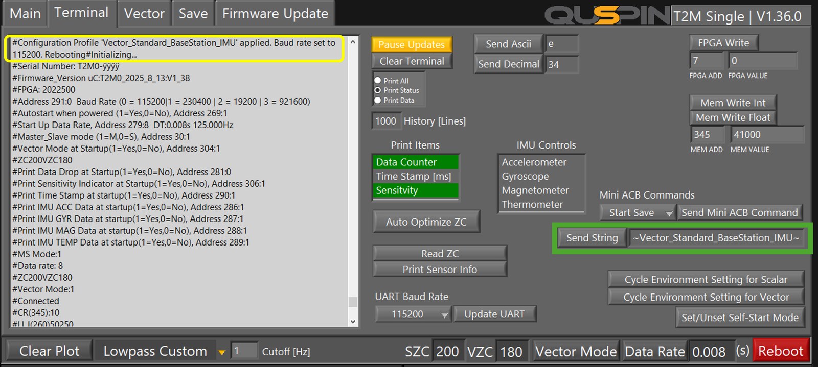
1. Confirmation message in the terminal.
2. Send String field where you paste the profile.
3. Location of cutoff[Hz]. This does not visually update when you send a configuration profile.
Important Formatting Note
The full string, including the tildes (~), must be sent as a single command. Do
not include any newline (\n) or carriage return (\r) characters.
Recommended & High-Performance Profiles
~Vector_Survey_Pro_MP~
The default profile on arrival for Magpies with the vector add-on. Recommended for moving platforms.
- Data Output Rate
- 250Hz
- Scalar / Vector Rate
- 500Hz / 83.3Hz
Key Settings: IMU (Acc/Gyr), Timestamp, Sensitivity
~V_Survey_Standard_IMU~
The default on arrival for sensors with the vector add-on. Recommended for moving platforms and compatible with ACB 2.0.
- Data Output Rate
- 125Hz
- Scalar / Vector Rate
- 500Hz / 83.3Hz
Key Settings: IMU (Acc/Gyr), Timestamp, Sensitivity
~Scalar_Pro_IMU_250Hz_MP~
The default profile on arrival for Magpies without the vector add-on. Recommended for moving platforms.
- Data Output Rate
- 250Hz
- Scalar / Vector Rate
- 1000Hz
Key Settings: IMU (Acc/Gyr/Mag), Timestamp, Sensitivity
~Scalar_Survey_Standard_IMU_125Hz~
The default on arrival for sensors without the vector add-on. Recommended for moving platforms and compatible with ACB 2.0.
- Data Output Rate
- 125Hz
- Scalar / Vector Rate
- 1000Hz
Key Settings: IMU (Acc/Gyr/Mag), Timestamp, Sensitivity
Standard Series (115200 Baud)
Compatible with the Standard Comms Board and Advanced Comms Board (ACB 2.0).
| Profile Name | Use Case | Output Rate | Scalar / Vector Rate | ZC | Meas Time | Filter | Prints | Sync |
|---|---|---|---|---|---|---|---|---|
~Scalar_Standard_MaxRate~ | Fastest scalar-only profile. | 500Hz | 1000Hz | SZC: 200 (Quiet) | - | LP: 200Hz | Data Drop Counter, Sensitivity | Master |
~Scalar_Survey_Standard_IMU~ | Scalar + full IMU data. | 250Hz | 1000Hz | SZC: 200 (Quiet) | - | LP: 100Hz | All IMU, Data Drop Counter, Sensitivity | Master |
~Scalar_Survey_Standard_IMU_Robust~ | Robust scalar + IMU for noisy environments. | 250Hz | 1000Hz | SZC: 100 (Average) | - | LP: 100Hz | All IMU, Data Drop Counter, Sensitivity | Master |
~Scalar_Survey_Standard_IMU_Slave~ | Slave for gradiometer pairing (scalar + IMU). | 250Hz | 1000Hz | SZC: 200 (Quiet) | - | LP: 100Hz | All IMU, Data Drop Counter, Sensitivity | Slave |
~Scalar_Survey_Standard_IMU_125Hz~ | Low-rate scalar + IMU. | 125Hz | 1000Hz | SZC: 200 (Quiet) | - | LP: 62Hz | IMU (Acc/Gyr/Mag), Timestamp, Sensitivity | Master |
~Scalar_Survey_Standard_IMU_125Hz_Slave~ | Low-rate slave for gradiometer pairing (scalar + IMU). | 125Hz | 1000Hz | SZC: 200 (Quiet) | - | LP: 62Hz | IMU (Acc/Gyr/Mag), Timestamp, Sensitivity | Slave |
~V_Survey_Standard~ | Primary vector profile for mobile surveys. | 250Hz | 500Hz / 83.3Hz | SZC: 200 (Quiet) | 300µs | LP: 100Hz | Timestamp, Sensitivity | Master |
~V_Survey_Standard_IMU~ | Vector + IMU; balanced for moving platforms. | 125Hz | 500Hz / 83.3Hz | SZC: 200 (Quiet) | 300µs | LP: 62Hz | IMU (Acc/Gyr), Timestamp, Sensitivity | Master |
~V_Survey_Standard_Robust~ | Robust vector profile for noisy environments. | 250Hz | 500Hz / 83.3Hz | SZC: 100 (Average) | 200µs | LP: 100Hz | Timestamp, Sensitivity | Master |
~V_Survey_Standard_IMU_Robust~ | Robust vector + IMU for noisy environments. | 125Hz | 500Hz / 83.3Hz | SZC: 100 (Average) | 200µs | LP: 62Hz | IMU (Acc/Gyr), Timestamp, Sensitivity | Master |
~V_Standard_Base~ | Vector base station (stationary mode 1). | 125Hz | 500Hz / 83.3Hz | SZC: 200 (Quiet) | 300µs | LP: 80Hz | IMU Temp, Timestamp, Sensitivity | Master |
~V_Standard_Base_IMU~ | Vector base station with full IMU data. | 125Hz | 500Hz / 83.3Hz | SZC: 200 (Quiet) | 300µs | LP: 80Hz | All IMU, Timestamp, Sensitivity | Master |
~V_Standard_Base_62Hz~ | Low-rate vector base station with IMU Mag/Temp. | 62.5Hz | 500Hz / 83.3Hz | SZC: 200 (Quiet) | 300µs | LP: 30Hz | IMU (Mag/Temp), Timestamp, Sensitivity | Master |
~Scalar_Standard_Base~ | Scalar base station. | 125Hz | 1000Hz | SZC: 200 (Quiet) | - | LP: 100Hz | IMU (Mag/Temp), Timestamp, Sensitivity | Master |
~Scalar_Standard_Base_IMU~ | Low-rate scalar base station with full IMU data. | 62.5Hz | 1000Hz | SZC: 200 (Quiet) | 300µs | LP: 30Hz | All IMU, Timestamp, Sensitivity | Master |
~Scalar_Standard_Base_32Hz~ | Ultra-low-rate scalar base station with IMU Mag/Temp. | 31.25Hz | 1000Hz | SZC: 200 (Quiet) | - | LP: 15Hz | IMU (Mag/Temp), Timestamp, Sensitivity | Master |
~V_Base_Auto~ | Self-optimizing vector base station (stationary). | 125Hz | 500Hz / 83.3Hz | Auto-Optimize | - | LP: 100Hz | Timestamp, Sensitivity | Master |
~Scalar_Base_Auto~ | Self-optimizing scalar base station (stationary). | 125Hz | 1000Hz | Auto-Optimize | - | LP: 80Hz | Timestamp, Sensitivity | Master |
~V_Standard_Base_Robust~ | Robust base station for noisy environments (mobile-optimized mode). | 125Hz | 500Hz / 83.3Hz | SZC: 200 (Average/Quiet) | 200µs | LP: 80Hz | Timestamp, Sensitivity | Master |
Pro Series (230400 Baud, 921600 Baud)
At 500 Hz, commands can be missed
On the two 500 Hz profiles the sensor spends most of its time formatting and sending data,
and an incoming command can be missed — most often when trying to leave the profile.
Send the command again; it usually takes on the second or third attempt. Sending
~Stop~ first, then your command, is the most reliable sequence. Stable vector
mode (command 227) is not available at 500 Hz; these profiles run in Survey mode.
Pro profiles ship in two baud variants. The name exactly as listed selects
230400 bps; append _MP before the closing tilde — e.g.
~Vector_Survey_Pro_MP~ — for the 921600 bps (Magpie)
variant.
Compatible with the Standard Comms Board. Not compatible with the Advanced Comms Board (ACB 2.0).
| Profile Name | Use Case | Output Rate | Scalar / Vector Rate | ZC | Meas Time | Filter | Prints | Sync |
|---|---|---|---|---|---|---|---|---|
~Scalar_Pro_MaxRate~ | Fastest scalar data rate (1000 Hz). | 1000Hz | 1000Hz | SZC: 200 (Quiet) | - | Off | Data Drop Counter, Sensitivity | Master |
~Scalar_Pro_IMU_500Hz~ | Scalar + IMU at 500 Hz output. | 500Hz | 1000Hz | SZC: 200 (Quiet) | - | LP: 240Hz | All IMU, Data Drop Counter, Sensitivity | Master |
~Scalar_Pro_IMU_250Hz~ | Scalar + IMU at 250 Hz output. | 250Hz | 1000Hz | SZC: 200 (Quiet) | - | LP: 100Hz | IMU (Acc/Gyr/Mag), Timestamp, Sensitivity | Master |
~Vector_Survey_Pro~ | Primary high-performance vector profile (mobile); standard cycle rate. | 250Hz | 500Hz / 83.3Hz | SZC: 200 (Quiet) | 300µs | LP: 100Hz | IMU (Acc/Gyr), Timestamp, Sensitivity | Master |
~Vector_Survey_Pro_1200~ | Vector profile at boosted cycle rate (300 Hz output). | 300Hz | 600Hz / 100Hz | SZC: 200 (Quiet) | 300µs | LP: 140Hz | IMU (Acc/Gyr), Timestamp, Sensitivity | Master |
~Vector_Survey_Pro_1400~ | Vector profile at maximum cycle rate (350 Hz output). | 350Hz | 700Hz / 116.7Hz | SZC: 200 (Quiet) | 100µs | LP: 160Hz | Timestamp, Sensitivity | Master |
~Vector_Survey_Pro_1400_IMU~ | Maximum cycle rate with IMU (175 Hz output). | 175Hz | 700Hz / 116.7Hz | SZC: 200 (Quiet) | - | LP: 80Hz | IMU (Acc/Gyr/Temp), Sensitivity | Master |
~Vector_Survey_Pro_Slave~ | Slave for gradiometer pairing; matches Pro survey settings. | 250Hz | 500Hz / 83.3Hz | SZC: 200 (Quiet) | 300µs | LP: 100Hz | IMU (Acc/Gyr), Timestamp, Sensitivity | Slave |
~Vector_Survey_Robust~ | Vector profile tuned for noisy environments. | 250Hz | 500Hz / 83.3Hz | SZC: 100 (Average) | 200µs | LP: 100Hz | All IMU, Timestamp, Sensitivity | Master |
~Vector_Survey_Robust_1200~ | Robust vector at boosted cycle rate for noisy environments. | 300Hz | 600Hz / 100Hz | SZC: 100 (Average) | 200µs | LP: 140Hz | All IMU, Timestamp, Sensitivity | Master |
~Vector_Survey_Robust_1400~ | Robust vector at maximum cycle rate for noisy environments. | 350Hz | 700Hz / 116.7Hz | SZC: 100 (Average) | 100µs | LP: 170Hz | All IMU, Timestamp, Sensitivity | Master |
~V_Pro_Base~ | Vector base station (stationary mode 1). | 250Hz | 500Hz / 83.3Hz | SZC: 200 (Quiet) | 300µs | LP: 100Hz | All IMU, Timestamp, Sensitivity | Master |
~V_Pro_Base_Robust~ | Robust vector base station (mobile-optimized mode). | 250Hz | 500Hz / 83.3Hz | SZC: 200 (Average/Quiet) | 200µs | LP: 100Hz | All IMU, Timestamp, Sensitivity | Master |
~Vector_Pro_Base_MP~ | Vector base station (stationary mode 1) at 921600 baud. | 250Hz | 500Hz / 83.3Hz | SZC: 200 (Quiet) | 300µs | LP: 100Hz | All IMU, Timestamp, Sensitivity | Master |
~Vector_Pro_Base_Robust_MP~ | Robust vector base station (Survey mode) at 921600 baud. | 250Hz | 500Hz / 83.3Hz | SZC: 200 (Average/Quiet) | 300µs | LP: 100Hz | All IMU, Timestamp, Sensitivity | Master |
~V_500Hz_Pro_MP~ | New in V1_46. Highest vector rate: 500 Hz total, 166.7 Hz per axis, each coil polarity output separately. Requires a Magpie or an equivalent 921600 baud link. Calibrate the vector coils first. | 500Hz | 1000Hz / 166.7Hz | SZC: 200 (Quiet) | 300µs | Off (filter in post) | Data Drop Counter, Sensitivity | Master |
~V_500Hz_Robust_MP~ | New in V1_46. Same 500 Hz rate with more averaging for noisy environments. Requires a Magpie or an equivalent 921600 baud link. Calibrate the vector coils first. | 500Hz | 1000Hz / 166.7Hz | SZC: 100 (Average) | 200µs | Off (filter in post) | Data Drop Counter, Sensitivity | Master |
Utility Commands
Special commands for controlling sensor state without changing survey parameters.
| Command | Function |
|---|---|
~Start~ | Enables automatic startup and reboots the sensor. |
~Stop~ | Disables automatic startup and reboots into an idle state. |
~Reset_EEPROM~ | Performs a factory reset of the sensor's memory. |
~Lock_Commands~ | Disables all standard single-character ASCII commands. Only ~profile~ and other ~utility~ commands will be accepted. |
~Unlock_Commands~ | Re-enables all standard single-character ASCII commands. |
~Reoptimize_Sensor~ | Runs the full reoptimization chain (light level, heading, laser gains) unattended, with the automatic reboots between stages. Allow 15 to 20 minutes. See the Reoptimization guide. |
~Reop_Laser_Gains~ | Re-tunes the laser lock gains without moving the sensor head; the laser is perturbed electronically. The laser lock error is shown in place of the magnetometer data while it runs. |
~Reop_Heading~ | Re-runs the heading (WL offset) optimization; starts once the cell has been locked for 5 minutes and saves automatically after the reboot. |
~Recalibrate_Vector_Coils~ | Vector add-on only. Runs the vector coil calibration and saves the result in one step (commands 6 then 9). Sensor locked, vector mode on, held still. |
Direct EEPROM Address Writes V1_44+
Not recommended for most users The built-in configuration profiles above cover almost every common use case — pick the closest match, optionally tweak a few individual settings via the QuSpin UI, and you are done. The direct-write commands documented in this section are intended for advanced users who script the sensor from a host stack, need to change just one or two settings without applying a full profile, or run with the sensor’s ASCII command lock enabled. If you are not sure whether you need this section, you probably don’t.
V1_44 firmware adds a family of tilde commands that write directly to the EEPROM addresses listed in the Configuration Settings Overview table at the top of this page.
Works with the command lock enabled
All tilde commands (the ones starting with ~) bypass the ASCII command lock. So
you can run with the sensor locked for safety against accidental decimal-command keystrokes
and still drive configuration changes through the shortcuts below.
Single-address write — ~ADDR,VAL~
Writes integer VAL to EEPROM address ADDR. Accepts any address in the uC
EEPROM range (0–400), so you can also poke advanced settings beyond the profile list.
Confirmation print: #EEPROM[ADDR] = VAL. Floats are not supported by this
shorthand — for the few float-valued addresses (laser PID gains, etc.) use the older
=ADDR\r\nVAL\r\n direct-write form which still works.
Examples
~30,1~— Master mode (address 30 = 1)~279,4~— Data rate 4 ms / 250 Hz output~290,1~— Enable timestamp print~291,3~— Baud rate selector to 921600 (reboot required for baud to take effect)~285,1~— 60 Hz notch filter preset
Coupled shortcuts — ~ADDR,VAL,PARAM~
A few configuration settings live across multiple coupled EEPROM addresses. Setting them one address at a time works, but the three-argument shortcuts below set the whole feature in one command.
| Shortcut | Writes | Meaning |
|---|---|---|
~285,8,fc~ | 285=8, 295=0, 296=fc | Custom Lowpass filter at fc Hz cutoff. Example: ~285,8,100~ sets a 100 Hz lowpass. |
~315,V,N~ | 315=V, 305=N |
VZC (Vector ZC) mode. V=0 auto, V=1 fixed; N is the count
when fixed. Example: ~315,1,200~ sets VZC fixed at count 200.
|
~353,V,S~ | 353=V, 355=S |
Fixed Measurement Time mode. V=0 off, V=1 on; S=1/2/3
selects 100/200/300µs. Example: ~353,1,3~ enables 300µs. (The
derived float at address 354 is recomputed by ~apply~ below.)
|
VZC Fixed and Fixed Measurement Time are mutually exclusive at runtime
If you enable both, Fixed Measurement Time wins — its logic runs later in the
vector-measurement chain and overwrites the VZC count. The firmware also prints a warning
when you set the second one, and the boot banner notes
#Fixed Vector Measurement Time Mode On, VZC Is Not Fixed. To clear either mode
use the three-argument form with V=0: ~315,0,0~ or
~353,0,0~.
Verify and apply — ~report~, then ~apply~ or ~Start~
~report~ prints every address listed in the EEPROM Address Reference table below
along with its current EEPROM value and a short friendly label. Use it to confirm what is
currently stored before applying the changes.
You have two ways to make the EEPROM changes take effect:
-
~apply~re-reads the EEPROM into the sensor’s live runtime variables without rebooting. Most everyday settings (print flags, data rate, ZC counts, vector mode, cycle rate) take effect on the next ISR tick. The Filter coefficients (285, 293–296) are reloaded by callingFilter_startup(), and the derived float at address 354 is recomputed from address 355. Baud rate (291) is the one setting that still requires a reboot — mid-session baud change would break the serial link unless the host coordinates a simultaneous switch. -
~Start~enables autostart-on-power (sets address 269 = 1) and reboots the sensor. The reboot picks up every EEPROM value cleanly from cold — including baud rate — and the sensor then runs the normal autostart sequence. Use this when you are done configuring and ready to start measurements.
Typical integrator workflow
- Send
~report~to confirm the sensor’s current state. -
Issue any number of
~ADDR,VAL~or~ADDR,VAL,PARAM~writes for the parameters you want to change. - Send
~report~again to verify the changes landed in EEPROM. -
Send
~apply~to push EEPROM into runtime without rebooting, or send~Start~to enable autostart and reboot — the sensor will pick up the new configuration from the EEPROM during startup and begin measurements.
EEPROM Address Reference
Every EEPROM address that corresponds to a setting in the
Configuration Settings Overview at the top of this page.
Sorted by address number. Use this table to find the right address for any
~ADDR,VAL~ or ~ADDR,VAL,PARAM~ write.
| Address | Setting | Command(s) | Encoding / Notes |
|---|---|---|---|
| — | Print configuration report | ~report~ | Print every address below with its current EEPROM value and a short friendly label. Does not change anything. |
| — | Apply EEPROM to runtime | ~apply~ |
Re-read EEPROM into live runtime variables without rebooting. Takes effect on the next
ISR tick for most settings. Baud rate (291) is the exception — use
~Start~ instead.
|
| 2 | Scalar ZC count (SZC) | ~2,N~ | Integer count. Typical: 40 (Noisy), 100 (Average), 200 (Quiet). Used when address 314=1. |
| 30 | Sync Mode | ~30,V~ | V = 0 Slave, 1 Master, 2 External PPS Sync, 3 Wireless GPS Sync |
| 269 | Auto-Start | ~269,0~ ~269,1~ | 0=off, 1=on (sensor begins measurements on power-up) |
| 279 | Data Output Rate | ~279,N~ | N = ms per output sample. Valid: 1, 2, 4, 8, 16, 32, 64, 128, 1000, 2000 |
| 281 | Print Data Drop counter | ~281,0~ ~281,1~ | 0=off, 1=on |
| 285 | Filter type | ~285,N~~285,8,fc~ (shortcut) | N = 0 Off, 1 Notch 60Hz, 2 Notch 50Hz, 3 Highpass 10Hz, 4 Highpass 20Hz, 5 Lowpass 10Hz, 6 Lowpass 20Hz, 7 Custom Notch (uses 293/294), 8 Custom LP/HP (uses 295/296). The 3-arg shortcut sets Custom Lowpass at fc Hz in one command (writes 285=8, 295=0, 296=fc). |
| 286 | Print IMU Accel | ~286,0~ ~286,1~ | 0=off, 1=on |
| 287 | Print IMU Gyro | ~287,0~ ~287,1~ | 0=off, 1=on |
| 288 | Print IMU Mag | ~288,0~ ~288,1~ | 0=off, 1=on |
| 289 | Print IMU Temp | ~289,0~ ~289,1~ | 0=off, 1=on |
| 290 | Print Timestamp | ~290,0~ ~290,1~ | 0=off, 1=on |
| 291 | Baud Rate selector | ~291,V~ | V = 0 (115200), 1 (230400), 2 (19200), 3 (921600).
Reboot required — use ~Start~ instead of
~apply~ after changing this.
|
| 293 | Custom Notch fu (Hz) | ~293,fu~ | Upper notch edge frequency. Used when 285=7. |
| 294 | Custom Notch fl (Hz) | ~294,fl~ | Lower notch edge frequency. Used when 285=7. |
| 295 | Custom LP/HP flag | ~295,0~ ~295,1~ | 0=Lowpass, nonzero=Highpass. Used when 285=8. |
| 296 | Custom LP/HP cutoff (Hz) | ~296,fc~ | Cutoff frequency. Used when 285=8. |
| 304 | Vector Mode | ~304,0~ ~304,1~ | 0=off, 1=on. Requires vector add-on. |
| 305 | Vector ZC count (VZC) | ~305,N~ | Integer count. Used when 315=1 and Fixed Measurement Time (353) is off. |
| 306 | Print Sensitivity (SI) | ~306,0~ ~306,1~ | 0=off, 1=on |
| 307 | ZC auto-opt flag | ~307,N~ | Internal flag for the SZC auto-optimization state machine. |
| 308 | ZC auto-opt mode | ~308,N~ | Internal flag for the SZC auto-optimization state machine. |
| 313 | ISR_INT | ~313,N~ | Internal ISR mode flag. |
| 314 | Scalar ZC Fixed | ~314,0~ ~314,1~ | 0=Auto-optimize, 1=Fixed (uses count at address 2) |
| 315 | Vector ZC Fixed | ~315,0~ ~315,1~~315,V,N~ (shortcut) | V = 0 Auto-optimize, 1 Fixed (uses count at address 305). The 3-arg shortcut sets both the flag and the count in one command (writes 315=V, 305=N). |
| 341 | Vector Mode Type | ~341,0~ ~341,1~ | 0=Survey (default, two averaged measurements), 1=Stable (single measurement, no coil calibration) |
| 345 | Cycle Rate | ~345,V~ | V = 10 Standard (1000Hz), 12 Boost (1200Hz), 14 Max (1400Hz) |
| 353 | Fixed Measurement Time Mode | ~353,0~ ~353,1~~353,V,S~ (shortcut) | 0=off, 1=on. When on, replaces VZC count for vector measurements. The 3-arg shortcut sets both mode and state in one command (writes 353=V, 355=S). |
| 354 | Fixed Measurement Time (seconds) | — |
Float. Derived from 355 by ~apply~ — do not write
directly via the integer shorthand.
|
| 355 | Fixed Measurement Time State | ~355,S~ | S = 1 (100µs), 2 (200µs), 3 (300µs) |
Tip: send ~report~ on a live sensor to see this same list with the current value
of each address inline. Quicker than checking against this table by hand.