Why Sync? & Choosing a Method
The QTFM2 operates using magnetic-field-producing coils within the sensor head to polarize the vapor between measurements. When deploying multiple sensors simultaneously, their respective fields can interfere with each other. The QTFM2 is designed to sync the clocks of multiple sensors, ensuring all coils are inactive during the measurement window — thus eliminating cross-sensor interference and letting the array act as a gradiometer.
Which timestamp to use
Everything below synchronises the sensors’ own clocks, and the
standard millisecond timestamp each QTFM streams (the > field) is the
time base your analysis should use — that is what sync makes comparable across
sensors. A Magpie or ACB additionally prepends its own microsecond timestamp; that is for
correlating to GPS time and monitoring dropped samples, not for measurement
timing. See
Serial Communication and Data
Format.
There are four ways to synchronize an array. All four keep the sensors’ measurement cycles phase-aligned; they differ in how the shared timebase is delivered. Methods 3 and 4 share the same underlying sensor mechanism (GPS Sync mode + 1 PPS + 11-byte UTC frame) and differ only in who supplies the host — a Magpie in Method 3, your own host in Method 4.
| Method | How the timebase is shared | Magpie? | Best for |
|---|---|---|---|
| Wired Master/Slave | One sensor (the master) outputs its clock on a Sync_Out pin; each slave receives it on Sync_In, daisy-chained with UMCC cables. Continuously hardware-locked. | No | Bench or fixed arrays where running a short clock cable between sensors is easy. Tightest sync. |
| External PPS Sync New | Every sensor locks its measurement cycle to a common external 1 PPS hardware pulse fanned out to each unit. Re-disciplined every second. | No | Arrays driven by a shared PPS source (a GPS receiver’s PPS output, a pulse/function generator, etc.). No clock wire between sensors, no absolute time. |
| Wireless GPS Sync Magpie | A QuSpin Magpie data logger with a GPS receiver forwards absolute UTC time to each sensor over its UART; the sensor disciplines its cycle to that. No clock wire between sensors. | Yes | Deployed / airborne / distributed arrays where a clock cable between sensors isn’t practical. Also tags every sample with absolute UTC time. |
| Sensor-Only GPS Sync New in V1_44 | Same as above but driven by your own host instead of a Magpie. You provide a 1 PPS edge and send an 11-byte UTC frame on the sensor’s main UART once per second. | No | Custom carrier integrations (drones, robots, fixed installations) where you want absolute UTC time stamping without taking a Magpie. Requires a small amount of host software. |
The individual serial commands referenced below (mode selects, sync-operation codes, LED behavior) are documented in full on the QTFM Gen-2 Quick Reference. This page covers the end-to-end workflow for each sync method.
FPGA hardware requirement (External PPS, Wireless GPS, and Sensor-Only GPS)
All three newer methods rely on FPGA features added in bitstream v5.05, and
the matching micro firmware is V1_43 or later (V1_44+ for Method 4). A
sensor that meets the requirement prints #FPGA 5.05 features in its boot banner.
FPGAs cannot be updated remotely. Unlike the micro firmware, the FPGA
bitstream can only be reprogrammed at QuSpin — it cannot be flashed in the field, over
USB, or via a customer firmware update. If your sensor was built before the v5.05 bitstream
was rolled in, External PPS Sync (cmd p/112) and GPS Sync (cmd
q/113) will be rejected by the sensor with an informative message and the
existing sync mode is left unchanged.
Two ways to get a v5.05+ sensor:
- Sensors purchased June 2026 or later ship with v5.05+ from the factory — no action required.
- Earlier sensors must be returned to QuSpin for an FPGA upgrade. Contact info@quspin.com to arrange the return; the upgrade itself is quick once the unit is on the bench.
The wired Master/Slave method (below) works on every Gen-2 sensor regardless of FPGA version, so it remains the right choice for arrays of older sensors.
Method 1 — Wired Master/Slave Sync
One sensor acts as the master and distributes its clock over a UMCC cable to one or more slave sensors. This is the original Gen-2 sync method and works on every sensor.
Step-by-step (two sensors)
- Identify the sync pins on the QTFM2 Comms board. On the Comms board (where
your USB cable connects), locate the UMCC pins labeled Sync_In and
Sync_Out (circled in red below).
The Sync_Out pin outputs the sensor’s clock; Sync_In receives a clock as input. The clock is a 0–3.3 V square wave at 50% duty cycle.
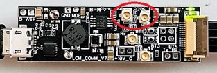
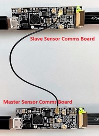
Sync_In / Sync_Out UMCC pins on the QTFM2 Comms board. - Connect the sensors. Use a UMCC cable from the Sync_Out pin of the
master sensor to the Sync_In pin of the slave
sensor. Don’t mix these up — the master provides the clock via Sync_Out, which
the slave receives via Sync_In.
Master Sync_Out → Slave Sync_In via a UMCC cable. - Set the slave sensor. Open the QuSpin User Interface, select the COM port
for the slave sensor, go to the Terminal tab, enter
!in the “Send Ascii” box and click Send Ascii. Confirm slave mode: the lower-left message readsSlave MS Mode:0, and an S appears in the top-right blue box on the Main tab. - Verify settings. Confirm both sensors have fully auto-started and operate normally, and that they have identical data rates and environmental settings.
- Finalize the sync. Switch the interface to the master sensor’s COM
port, go to the Terminal tab, and send the Ascii character
T. Look for a#Sensors Sync Completemessage in the lower-left corner. The LED indicators on all sensor ECUs should then display synchronized color patterns, confirming the sync.
Syncing more than two sensors
Use one master and designate the rest as slaves, daisy-chaining the clock:
- Connect Sync_Out of the master to Sync_In of the first slave.
- Connect Sync_Out of the first slave to Sync_In of the next slave.
- Repeat until all sensors are connected.
- Set each slave (step 3) and finalize from the master (step 5).
Vector-mode spacing Even when synced, sensors running in vector mode can still experience interference from the vector coils of nearby sensors. For vector configurations, keep sensors at a greater distance from each other.
Method 2 — External PPS Sync New in V1_43
Each sensor disciplines its measurement cycle to a shared external 1 PPS (one-pulse-per-second) hardware signal. Fan the same PPS out to every sensor, and they all lock their cycles to the same edge — synchronized, with no clock wire between sensors and no Magpie required. There is no absolute time in this mode; the shared edge provides the alignment.
Requires FPGA bitstream v5.05+ Sensors built before June 2026 typically ship with an earlier bitstream and must be returned to QuSpin for the upgrade — it cannot be done remotely. See the full FPGA hardware requirement at the top of this page. The wired Master/Slave method works on every Gen-2 sensor if you can’t upgrade.
What you need
- Sensors with FPGA bitstream v5.05+ and firmware V1_43+ (boot banner shows
#FPGA 5.05 features). - A common 1 PPS source — a 0–3.3 V pulse, once per second — fanned out to each sensor’s external sync (PPS) input. This is the same input used by the legacy Master/Slave clock.
One-time setup (per sensor — both settings persist across reboot)
- Select External PPS Sync mode: send command
112(p). The sensor confirms#External_PPS_Sync MS Mode:2. Saved to EEPROM. - Enable periodic re-arm + auto-engage: send command
230. Saved to EEPROM. This does two things: it keeps the sensor re-aligned to the PPS edge over long runs, and it tells the sensor to bring itself into sync automatically after cell-lock whenever a valid PPS is present.
After this one-time setup, every time the sensor powers on it autostarts, locks its cell,
detects the PPS, and engages sync on its own — no commands needed at
power-up. It prints #PPS sync auto-engaged … when it does.
Verify the sensor is locked to the PPS
Send command 234 to toggle the approx. 1 Hz PPS status debug line:
#PPS dbg: M_S=2 alive=1 consec=12 edges=1234 dt=4ms offset=27 locked=1 ra=0 resume_n=0
The line is reprinted once per wall-clock second so you can watch it converge. Send
234 a second time to turn the stream off (the sensor confirms with
#PPS status debug: OFF).
What each field means
| Field | Meaning | What you want |
|---|---|---|
M_S=N |
Sensor sync mode. 2 = External PPS Sync, 3 = wireless GPS
Sync, 1 = wired Master, 0 = wired Slave. Confirms the sensor
is actually in the mode you set with command 112.
| 2 for External PPS |
alive=N | 1 if a valid PPS edge has been seen within the last 2.5 s, 0
if not. This is an electrical “the input is reaching me” check — it
doesn’t say anything about edge timing quality, only that something is
pulsing on the sync input.
| 1 while sync is in use |
consec=N |
Consecutive valid-rate PPS edges in a row. Increments only when each edge arrives at
roughly 1 Hz (within the approx. 1 s validity window). An off-cadence edge resets the run to
1; a full dropout drops it to 0. Caps at 99. The
fastest single-field signal that “my PPS source is clean and steady.”
| Climbing and not resetting |
edges=N | Cumulative count of valid external PPS pulses observed since the sensor booted. Read directly from the FPGA’s PPS counter — only steps when a real pulse arrives. Watching it for a few seconds confirms the source rate: it should advance by 1 each second. | +1 per second |
dt=N ms |
Milliseconds since the last PPS edge, captured at the moment this print line fires. The
print fires once per wall-clock second, so dt lands wherever in
0–1000 ms the previous edge happens to sit relative to the print rhythm. A steady
value is normal: it just means the print and the PPS are running at
slightly different rates and the relative phase is stable on this timescale.
This is NOT the inter-PPS interval and does not indicate the source
rate.
| Any value < 2500 (= no dropout) |
offset=N |
The FPGA’s measured phase offset between the sensor’s measurement cycle and
the PPS edge, in 160 MHz ticks (1 µs = 160 ticks,
1 ms = 160000 ticks). The raw value is printed; the FPGA’s internal
interpretation wraps values above 80000 around to a “negative” offset (cell
is ahead of the PPS edge), so a printed offset=110000 is effectively
−50000 ticks ≈ −0.31 ms. This is the signal the FPGA’s
edge-pull works against.
| Inside [15, 35] ticks (≈ 100–200 ns) when locked |
locked=N | 1 when offset is inside the [15, 35] tick window (the
sub-µs lock condition), 0 otherwise. This is the firmware’s
“I am edge-locked to the PPS at fraction-of-a-µs precision” flag. It
is the right indicator for absolute PPS-aligned timestamping. It is NOT
required for cross-sensor sync — see the note below.
| 1 for absolute lock |
ra=N |
The arming state for the operator-driven realign (commands 231 / 232 / 233 — NOT
the periodic re-arm from 230). 0 = idle (no realign pending),
1 = NEXT (will fire on the next edge — set by 231),
2/3/4 = dropout-mode states (set by 232). After
a one-shot fires it returns to 0 automatically.
| 0 in steady state |
resume_n=N |
Edges counted since PPS resumed during an active cmd-232 dropout-mode realign. Only
meaningful while ra is in the dropout sequence. In steady state this is the
residual value from a previous 232 — safe to ignore.
| Don’t worry about it outside an active 232 |
If you only care about cross-sensor sync, locked=0 is OK
Cross-sensor coincidence comes from sharing the same PPS and broadcasting cmd
231 on a common edge — every sensor that receives that broadcast within
one PPS second realigns its data counters at the same instant, so the Bx/By/Bz
samples coincide across the array. The locked=1 flag is the additional
signal that each individual sensor’s cell phase has also been pulled to within a
sub-µs window of the PPS edge — useful if you want absolute PPS-tagged
timestamps, but not strictly necessary for sensor-to-sensor coincidence. Enable command
230 on each sensor to engage the active edge-pull and reach locked=1
automatically after cell-lock.
Reading offset: don’t confuse the units with dt
The ms suffix in the print line belongs to dt, not
offset. offset is in 160 MHz ticks: divide by
160 to convert to µs (so offset=27 ≈ 0.17 µs,
offset=110000 ≈ 688 µs ≈ −312 µs after
wrap).
Realigning the array
“Realign” resets each sensor’s millisecond timestamp, restarts its averaging window, and (in vector mode) makes the Bx/By/Bz samples coincide. Because all sensors share the same PPS, triggering a realign on a common edge lines them all up at the same instant. Two one-shot options:
| Cmd | Action | Use |
|---|---|---|
| 231 | Realign on next PPS | Realigns on the very next valid PPS edge, then disarms. Broadcast this to every sensor within one PPS second and they all realign on the same edge. |
| 232 | Realign after PPS dropout | After arming, briefly disconnect the shared PPS; when it resumes, every sensor realigns on the 3rd valid edge, then disarms. Cutting and restoring one shared line realigns the whole array with no per-sensor command. |
| 233 | Disarm | Cancels a pending realign armed by 231 or 232. |
Both arming modes are one-shot — once they fire they disarm and never re-arm on their own, so a realignment is never forced unintentionally.
Method 3 — Wireless GPS Sync Magpie only
A QuSpin Magpie data logger with an onboard GPS receiver forwards GPS-derived absolute UTC time to each sensor over its UART. The sensor disciplines its measurement cycle to that time — so an array stays synchronized with no clock wire between sensors, and every sample is tagged with absolute UTC. This method requires a Magpie (firmware V5.10 or later).
Requires FPGA bitstream v5.05+ Like External PPS, this method depends on FPGA features that cannot be flashed remotely. Sensors purchased June 2026 or later already have it; earlier units must be returned to QuSpin for the upgrade. See the full FPGA hardware requirement at the top of this page. The wired Master/Slave method works on every Gen-2 sensor if you can’t upgrade.
Hardware prerequisites
- A QuSpin Magpie (firmware V5.10+) connected to the QTFM sensor (the existing connection also carries the sync line — no new wiring required).
- The Magpie’s GPS antenna has a clear sky view; at least 4 satellites for a valid time fix.
- Sensor FPGA bitstream v5.05+ and firmware V1_43+ (boot banner shows
#FPGA 5.05 features).
Turnkey setup — two Magpie commands, no sensor commands
Recommended
Send [GPS on] then [gps_sync_auto on] to the Magpie. In auto mode
the Magpie does the entire sensor-side setup for you — it waits for the GPS fix, polls
the sensor until it reports cell-locked, then sends the sensor commands
113 → 206 → 209 → 230 over the UART and begins forwarding UTC.
You don’t send any commands to the sensor.
# On the Magpie (one time — persists across reboots):
[GPS on]             → power on the Magpie's GPS receiver
[gps_sync_auto on]   → start the turnkey auto-arm sequence

# Monitor progress at any time:
[gps_sync status]
Send these to the Magpie over its Wi-Fi terminal, Bluetooth terminal, or USB console.
Magpie sync commands
| Magpie Command | Purpose |
|---|---|
[GPS on] | Powers on the Magpie’s GPS receiver (off by default to save power). Check the fix with [GPS status]. |
[gps_sync_auto on] Turnkey |
Fully automatic mode (recommended). Waits for GPS fix, polls the sensor until
cell-locked, then sends 113 / 206 / 209 / 230 and forwards UTC frames. Persists across
reboots. Requires [GPS on] first.
|
[gps_sync on] Manual |
Forwards UTC frames only; you configure the sensor yourself (send sensor cmds 113
→ 206 → 209 → 230). Requires [GPS on] first.
|
[gps_sync status] | Reports mode (OFF / manual ON / AUTO), auto-arm state, GPS fix, and sensor autostart / cell-lock state. |
[gps_sync off] |
Turns sync off — stops UTC forwarding and resets the auto-arm. GPS receiver stays
on (use [GPS off] to power it down).
|
Manual alternative (configure the sensor yourself)
If you prefer to drive the sensor: send [gps_sync on] (manual) on the Magpie, then
once the sensor has finished autostart send it: 113 (GPS Sync mode) →
206 (enable sync) → 209 (arm edge) → 230
(periodic re-arm, recommended for long runs).
Verification
- Watch the sensor LED. Once synced and the data is good, the ECU LED is
solid white (red = the current measurement is flagged bad). For a
multi-sensor visual check you can switch to a per-second rainbow with sensor command
235— all properly synced sensors then step through the same color at the same instant. (The rainbow is troubleshooting-only; it adds a small 1 Hz magnetic signature and reverts to white on reboot.) -
[gps_sync status]showsAUTO (turnkey)withAuto-arm state: ARMEDandSensor cell locked: YESwhen complete.
UTC time frame (technical reference)
For reference, the Magpie forwards absolute UTC time as an 11-byte binary frame over the sensor’s UART once per second:
| Byte | Field | Description |
|---|---|---|
| 0 | Sync byte 1 | 0xAA — start of frame. |
| 1 | Sync byte 2 | 0x55 — confirms frame intent. |
| 2–9 | UTC milliseconds | 64-bit unsigned, big-endian. Absolute Unix-epoch milliseconds. |
| 10 | CRC-8 | CRC-8 over bytes 2–9 (poly 0x07, init 0x00, no reflection). |
Most users never touch the frame directly — the Magpie generates it. It’s documented here for anyone building a custom UTC source. Receiving a frame while the sensor’s sync subsystem is off (cmd 206 not sent) is a harmless no-op.
To exit GPS Sync
Send [gps_sync off] to the Magpie (stops UTC forwarding; the sensor’s
periodic re-arm self-suppresses within approx. 3 s). Optionally, on the sensor send
space (Master) or ! (Slave) to return to a legacy mode — the
mode is saved to EEPROM.
Method 4 — Sensor-Only GPS Sync New in V1_44
Same underlying sensor sync mode as Method 3, but driven by your own host instead of a Magpie. The sensor’s main UART now accepts the same 11-byte UTC frame on a non-Magpie line, so you can integrate the QTFM into a custom carrier (drone, robot, fixed installation) without a Magpie in the loop. You provide the 1 PPS edge and a host that can read your GPS receiver’s NMEA time and pack it into the frame.
Requires FPGA bitstream v5.05+ and sensor firmware V1_44+ Same FPGA requirement as Method 3. V1_44 added the ability to receive the UTC frame on the sensor’s main UART; earlier firmware only accepted it on the dedicated Magpie UART. See the FPGA hardware requirement at the top of this page.
What you need
- A 1 PPS source wired to the sensor’s PPS sync input — the same input used for External PPS Sync (Method 2). Typically a GPS receiver’s 1 PPS output (0–3.3 V edge).
- A UTC time source that your host can read — typically the NMEA stream from the same GPS receiver. The host’s job is to turn the NMEA time into absolute Unix-epoch milliseconds and pack it into the 11-byte frame.
- A serial connection from your host to the sensor’s main UART (the same UART used for normal commands and data) at the sensor’s configured baud rate. 921600 is recommended for the lowest serial latency.
-
Sensor FPGA v5.05+ and firmware V1_44+. Boot banner shows
#FPGA 5.05 featuresand the firmware version line showsV1_44or later.
Workflow
- One-time sensor configuration. Send to the sensor:
113— select GPS Sync mode (FPGA addr 30 = 3). Saved to EEPROM.206— enable the GPS sync subsystem. Response:#GPS Sync: ENABLED.230— enable periodic auto-engage so subsequent reboots come back synced automatically. Saved to EEPROM.
- Wire up the 1 PPS from your GPS receiver to the sensor’s PPS sync
input. The sensor will start counting PPS edges as soon as they appear; verify with sensor
command
234(the#PPS dbg:stream —edgesfield should advance once per second). - On your host, once per UTC second, send an 11-byte frame to the
sensor’s main UART:
Byte Field Value 0 Sync byte 1 0xAA1 Sync byte 2 0x552–9 UTC milliseconds 64-bit unsigned, big-endian. Absolute Unix-epoch milliseconds. 10 CRC-8 CRC-8 over bytes 2–9 (poly 0x07, init0x00, no reflection).Send the frame within roughly 100 ms of the PPS edge it corresponds to — before or after, doesn’t matter. The sensor pairs the frame’s UTC value with the most recent PPS edge it saw, so loose timing is fine.
- Verify the sync. See the verification section below.
CRC-8 reference implementation
For a quick host-side check — standard CRC-8 with polynomial 0x07, init
0x00, no input/output reflection. Run it over the 8 UTC payload bytes (positions 2
through 9 of the frame):
uint8_t crc8(const uint8_t *data, int len) {
    uint8_t crc = 0;
    for (int i = 0; i < len; i++) {
        crc ^= data[i];
        for (int b = 0; b < 8; b++) {
            crc = (crc & 0x80) ? (uint8_t)((crc << 1) ^ 0x07)
                                : (uint8_t)(crc << 1);
        }
    }
    return crc;
}
Verification
Enable the PPS debug stream with sensor command 234 — it prints once per second:
#PPS dbg: alive=1 edges=1234 dt=1000ms offset=27 locked=1 mode=0 resume_n=0What to look for as you bring the system up:
-
alive=1andedgesadvancing — your PPS is reaching the sensor. If not, check the wiring and signal level (0–3.3 V edge). -
Send
206if you haven’t already, then look at the response lineUTC frames received so far: good=N bad=N.goodshould climb once per second,badshould stay at 0. Ifbadis climbing, the frame format or CRC is wrong; if both stay at 0, the host isn’t sending bytes (or wrong baud). -
locked=1— the sensor’s cycle is now sub-microsecond aligned to your PPS edge. May take a few seconds after cell-lock completes.
Things to keep in mind
- The UART frame alone does not provide phase lock. It provides absolute time stamping. The actual phase alignment of the sensor’s measurement cycle comes from the 1 PPS edge on the sync input pin. Without a real PPS edge, the sensor will still receive UTC frames but the cycle won’t align.
- The same UART carries normal commands and data. Hardware UART is full-duplex, so the sensor’s measurement output stream (sensor → host) and your UTC frames (host → sensor) don’t collide. Avoid sending other commands within approx. 100 ms of when you’ll be sending a UTC frame to keep things tidy.
- Stray
0xAAbytes are safe. A malformed or partial frame counts as a bad frame after a 10 ms timeout and is discarded; normal command processing resumes immediately. - No Magpie required, no Magpie commands. Everything happens between your host, the sensor’s main UART, and the PPS input.
To exit Sensor-Only GPS Sync
Send space (Master) or ! (Slave) to the sensor — the mode is
saved to EEPROM and the sensor returns to that mode on the next reboot. Stopping the
host’s UTC frame stream alone does not exit the mode — the sensor stays in GPS Sync
mode but reports the lack of frames as falling counters in the debug stream.
Appendix — Running Multiple QuSpin UI Instances
To monitor several sensors on one PC at the same time, run a separate copy of the QuSpin User Interface for each.
-
Open the folder containing the installed QuSpin UI (by default
C:\Program Files (x86)\QuSpin\QTFM2_UI). -
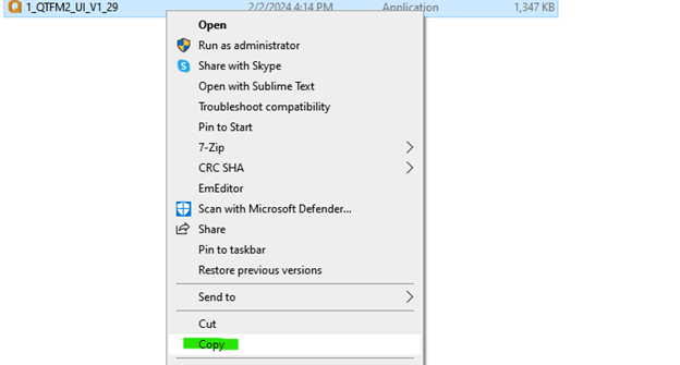
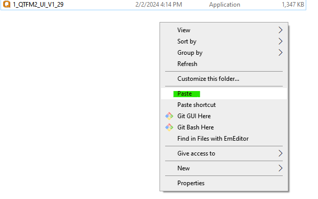
Copy the
QTFM2_UIapplication and paste it back into the same folder (right-click → Copy, then right-click → Paste). - Make as many copies as you have sensors. Double-click each copy to launch an independent UI, then connect each to its own sensor’s COM port.