Part 1 · Hardware Setup
Core hardware components
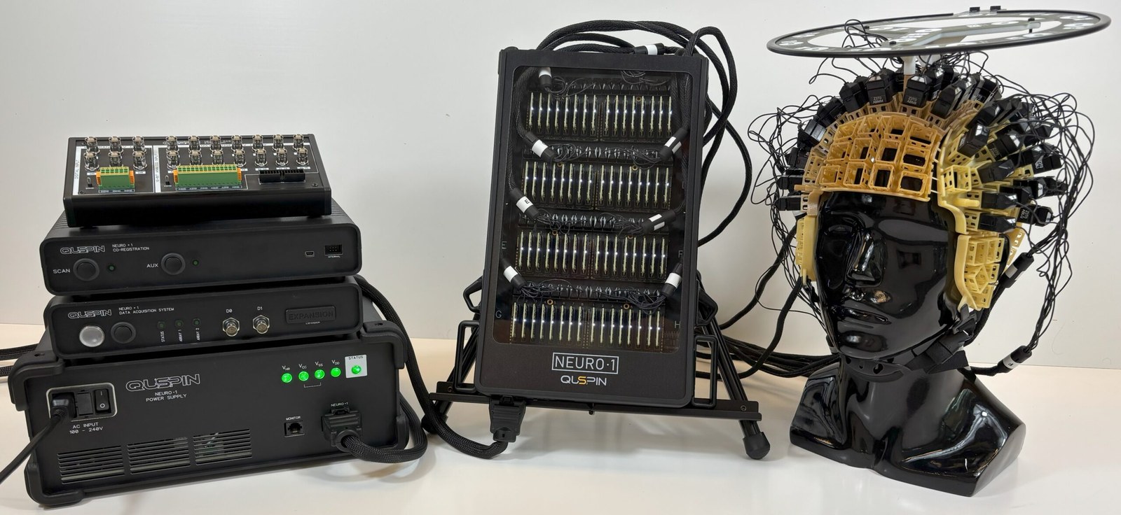
Four components work together: the PSU powers the backpack, the DAQ links it to your PC, and the sensors capture the data.
Power Supply Unit (PSU)
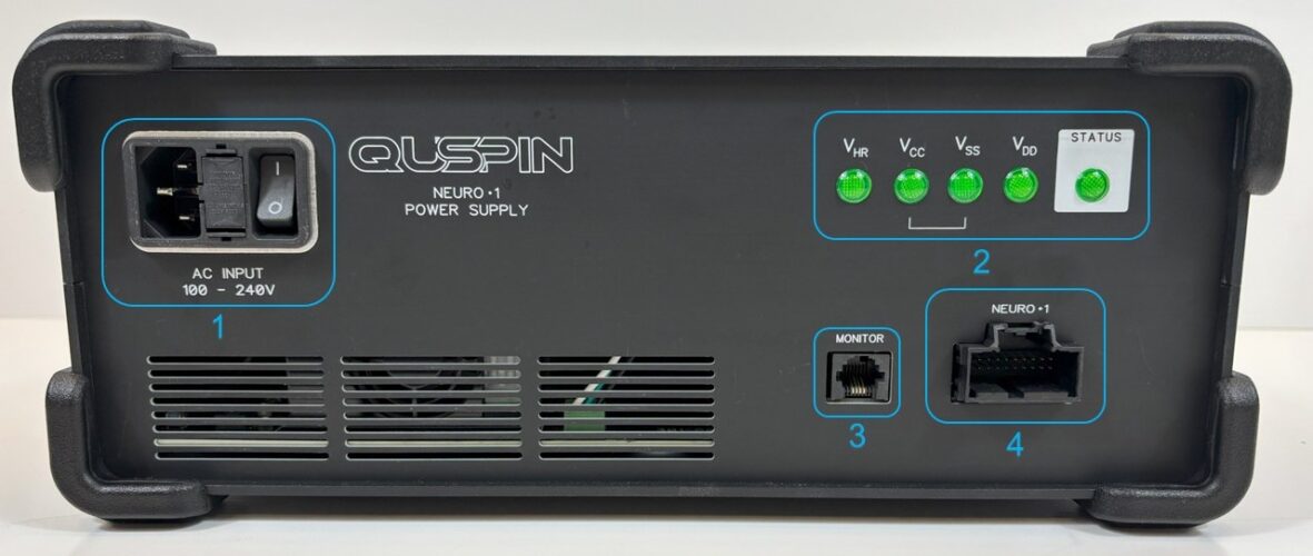
Delivers stable power to the backpack module housing all sensor control electronics, with intelligent power management and system monitoring.
Data Acquisition Module (DAQ)
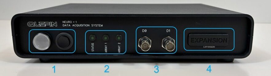
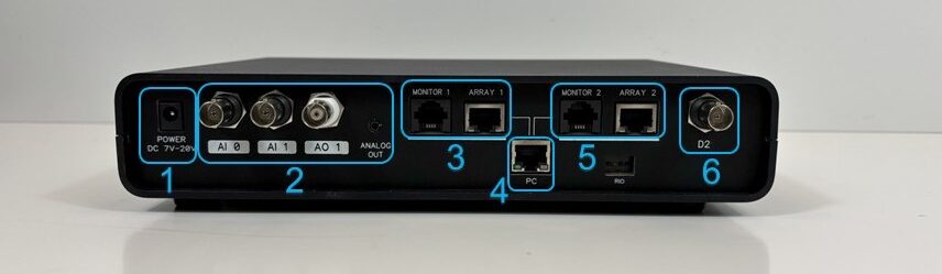
The communication hub between your PC and the hardware — high-speed data transfer, system control, and real-time monitoring.
Backpack Module
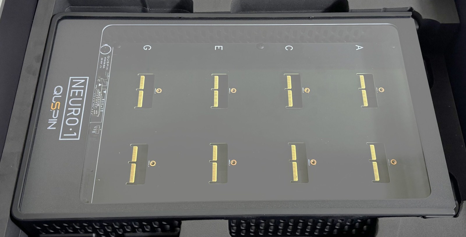
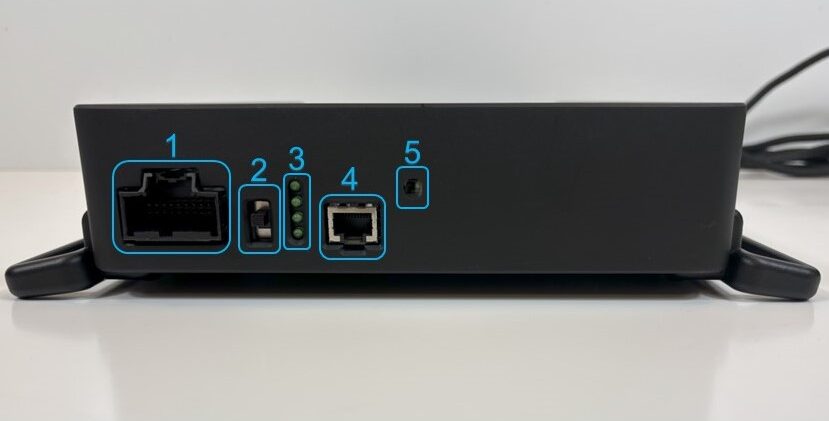
Holds up to 8 modules (A–H), each hosting up to 8 cardmags — up to 64 sensors per backpack. Multiple backpacks synchronize to build larger arrays.
Sensors & Control Electronics
The precision measurement components that capture neurological data. Covered in detail after the initial hardware and software setup.
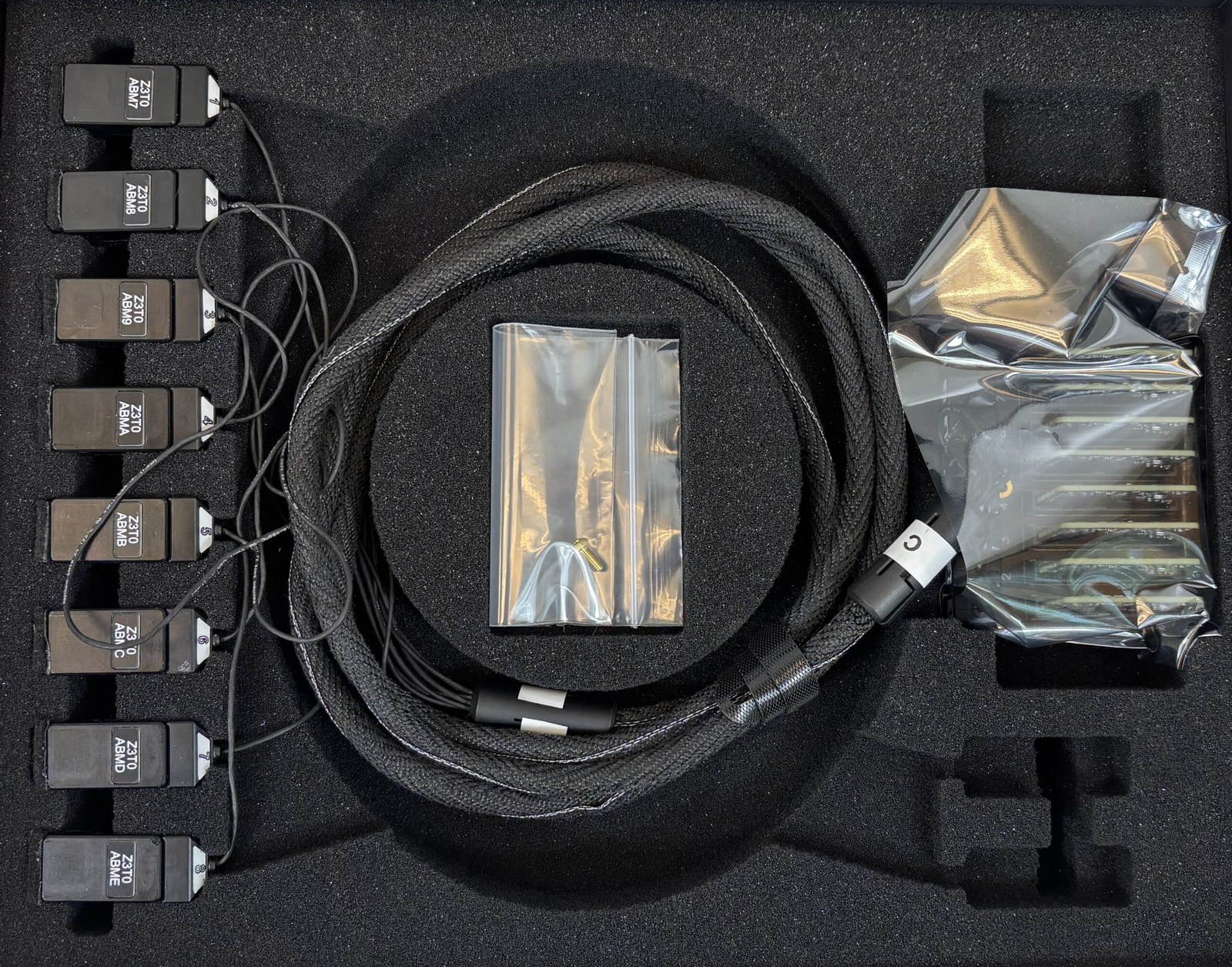
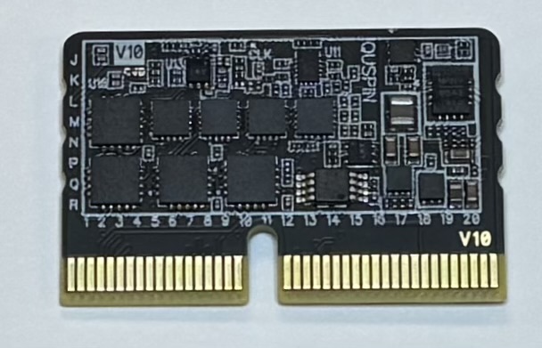
The PSU powers a backpack running up to 64 sensors. The DAQ manages communication between the PC and sensor electronics and lets multiple backpacks synchronize into larger arrays — reliable, scalable, research-grade acquisition.
Setup instructions
Leave the sensors and control electronics aside until this initial setup is complete. Follow along with the video or the steps below.
Unbox the PSU, DAQ, backpack, and cables. Set the sensors and sensor control electronics aside for now.
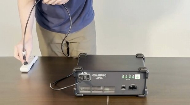
Power the PSU by connecting the AC power input to a 100–240 V outlet.
Turn the PSU power switch ON (up). The STATUS LED blinks, then turns solid. Other LEDs stay off until the backpack is connected.
Turn the PSU power switch back OFF (down) before cabling.
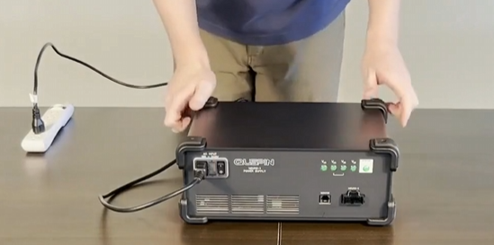
Power the DAQ with the provided 19 V supply. Wait for the Status LED to blink slowly—boot can take up to 3 minutes. The DAQ is designed to stay powered on.
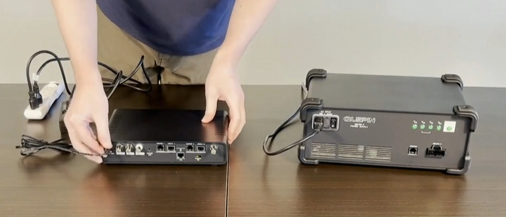
Connect the PSU “Monitor” port to “Monitor 1” on the DAQ with the provided RJ11 cable—this lets the Neuro‑1 UI or the backpack switch control the PSU.
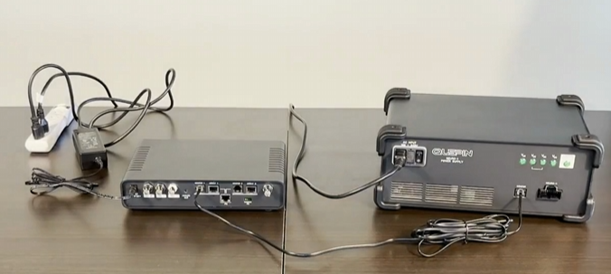
Connect the DAQ “PC” port to an ethernet port on the PC (black cable; use the provided ethernet‑to‑USB adapter if needed).
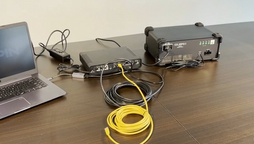
Connect “Array 1” on the DAQ to the ethernet port on the backpack—the data connection. (Module installation is covered in the Running Sensors guide.)
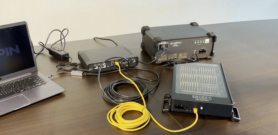
Connect the PSU “Neuro‑1” port to the backpack using the provided power cable.
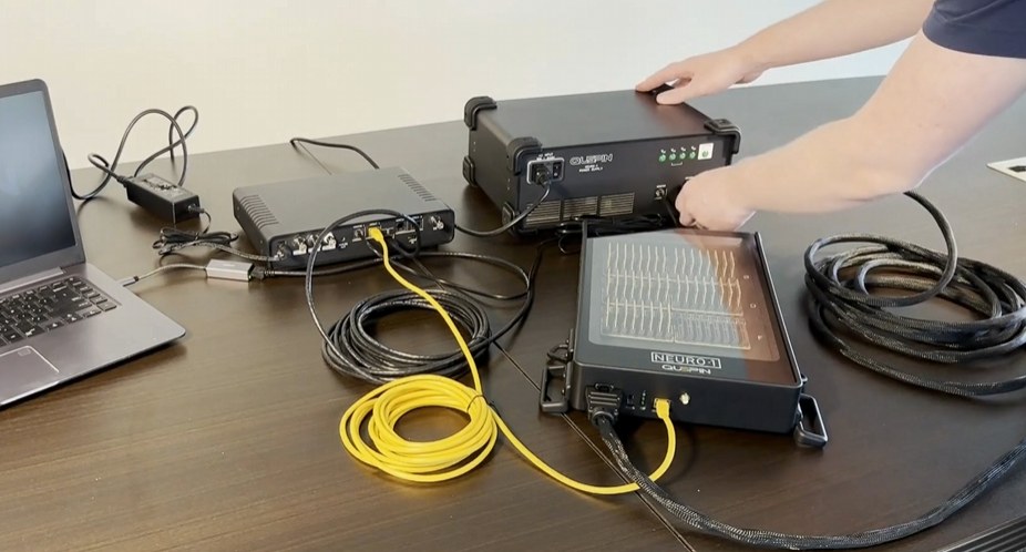
Turn the PSU power switch back ON (up position).
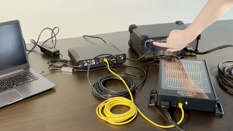
Turn the power switch on the front of the backpack ON (up). The 4 remaining LEDs on the PSU and the 4 LEDs on the backpack should all light green. Initial hardware setup is complete.
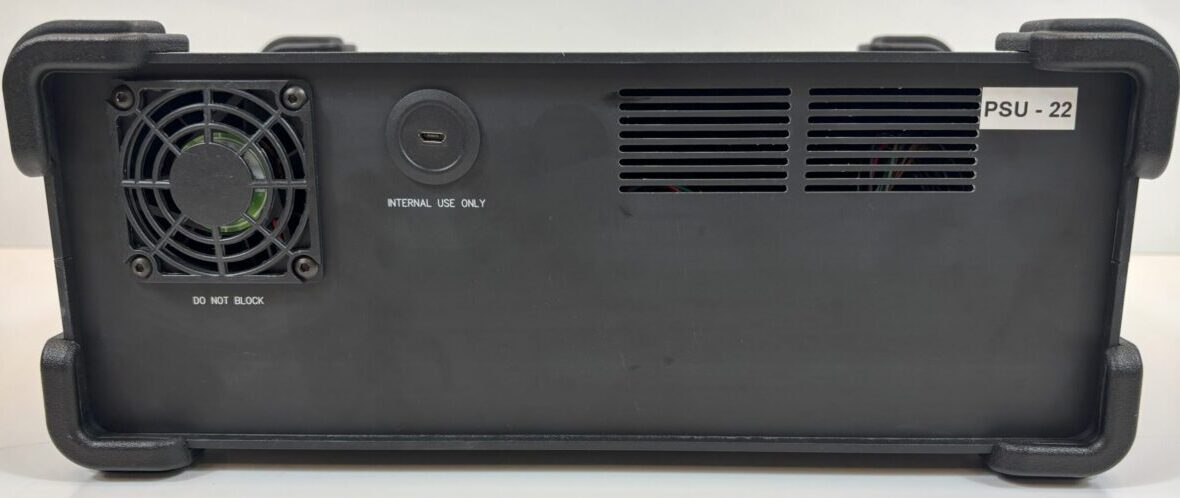
Ensure proper ventilation clearance around all sides. Refer to the numbered callouts in figures for component identification. Contact our hardware team for detailed specifications and support.
Part 2 · Software Setup
Software solutions
N1 User Interface
Convenient control of the N1 system — power, status, configuration, and recording.
Previous version: N1 UI V4_65 (7/31/2024)
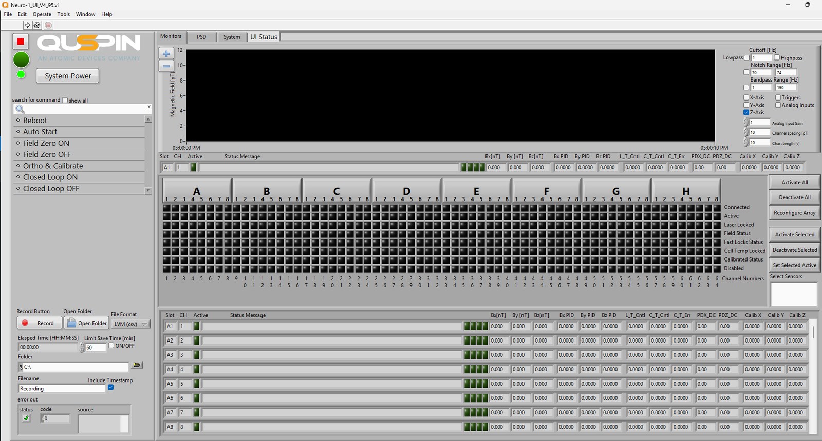
First-time setup checklist
- 1 Download and run the 32‑bit Runtime Engine and DAQ Drivers installer.
- 2 Download and run the latest Neuro‑1 User Interface.
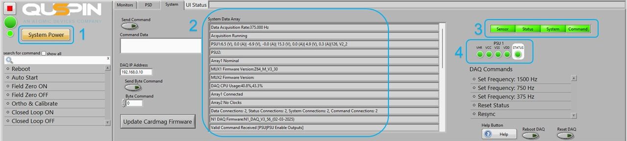
- 3 Verify PSU power on/off works via the “System Power” button, top-left of the UI (1).
- 4 In the “System” tab, verify data is visible in the System Data Array (2).
- 5 Confirm Sensor, Status, System, and Commands LEDs are green (3)—DAQ communications good.
- 6 Confirm VHR, VCC, VSS, VDD LEDs are green (4)—PSU1 voltages good.
N1 Data Viewer
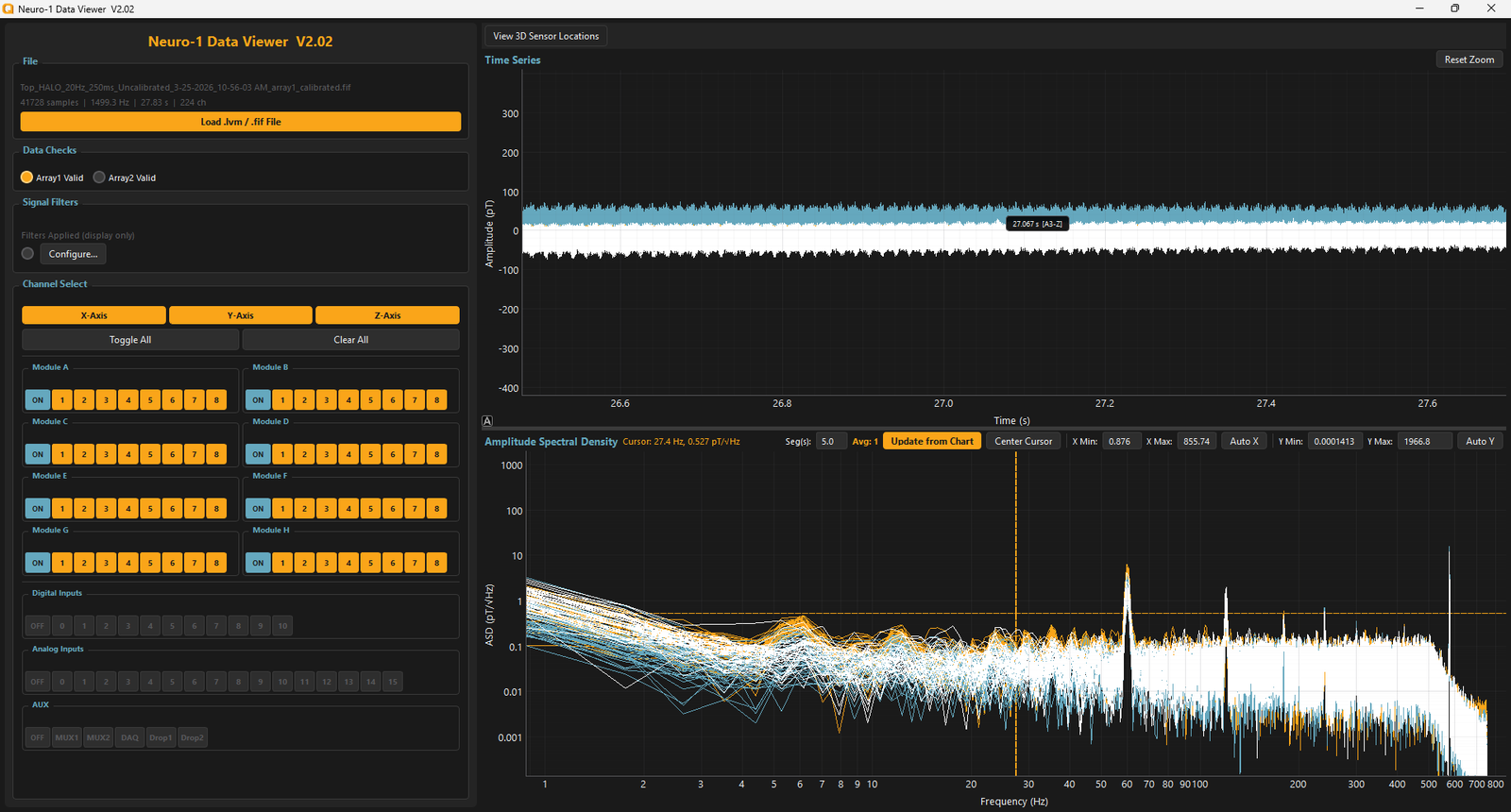
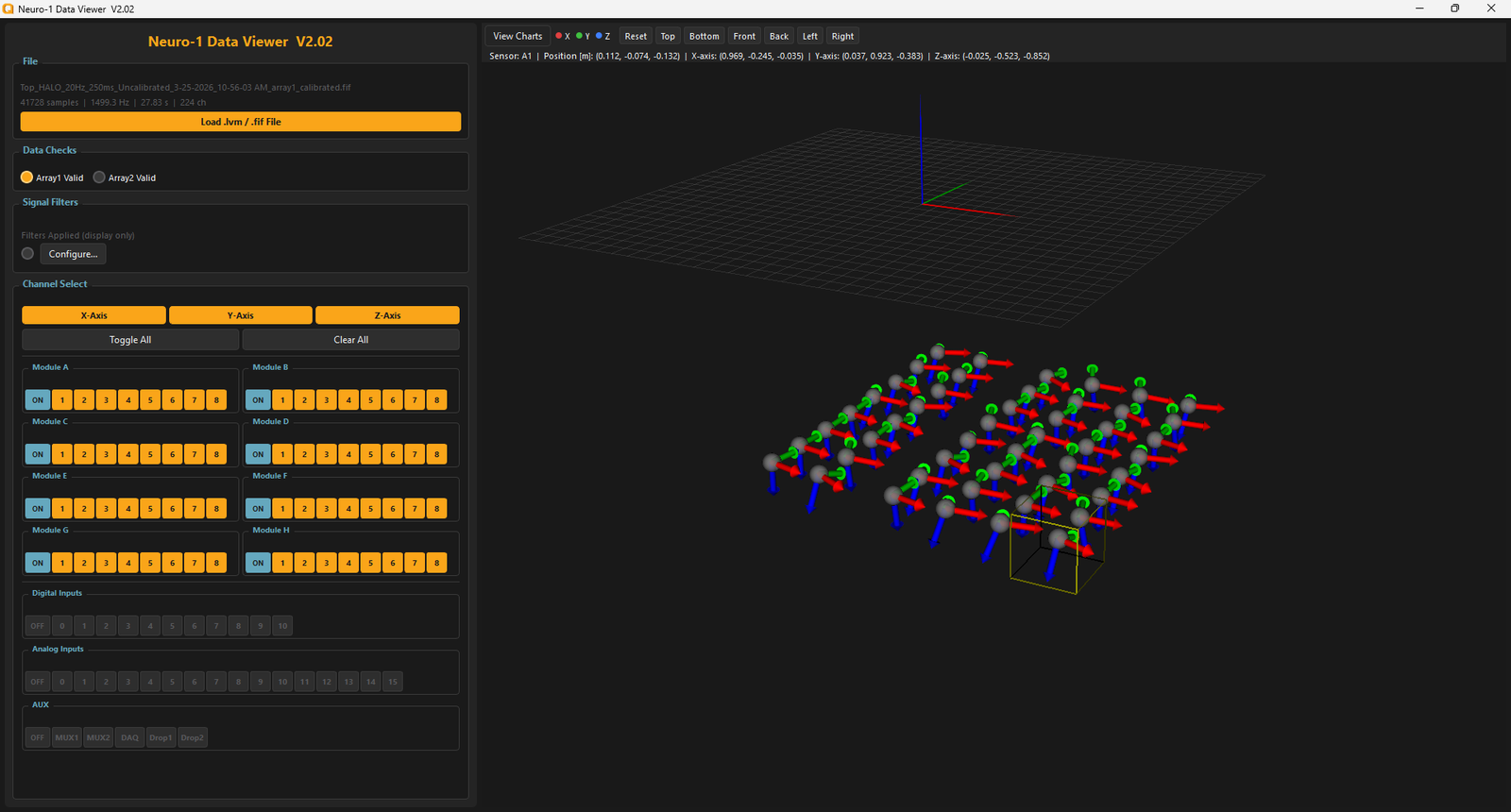
Convenient viewing of N1 recordings, including chart and 3D model views.
Previous versions: V2_01 (03/10/2026) · V1_55 (07/23/2025) · 64-bit Runtime + DAQ Drivers
Part 3 · Running Sensors
Connect and run sensors
Important: before handling sensors or sensor control electronics (modules and cardmags), take basic ESD precautions — ground yourself to remove excess electrical charge and avoid damaging sensitive electronics.
Component overview
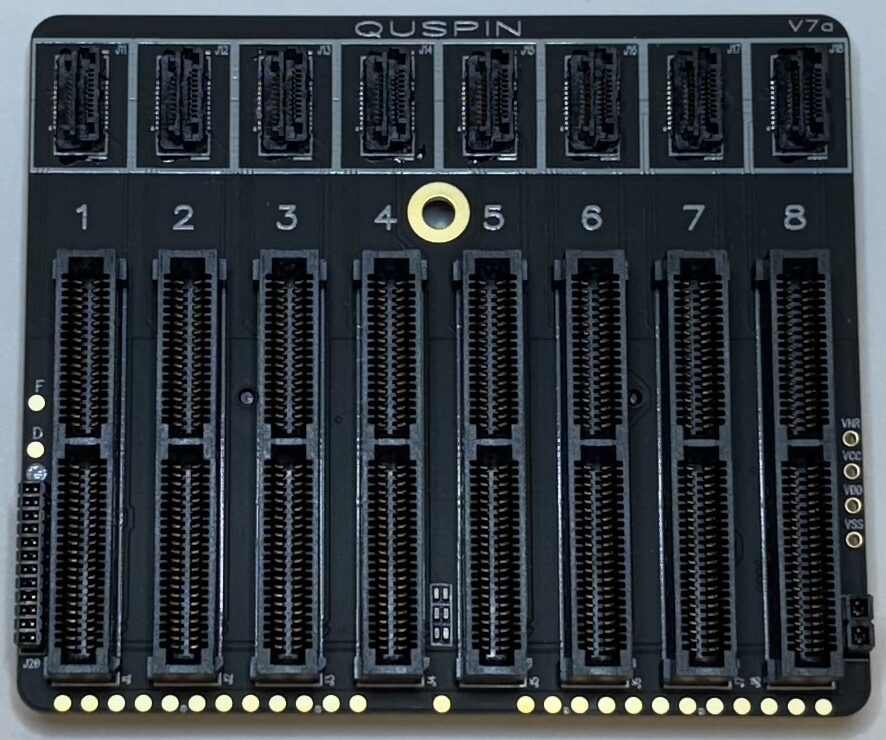
Central processing for 8 sensor channels
Individual sensor control electronics
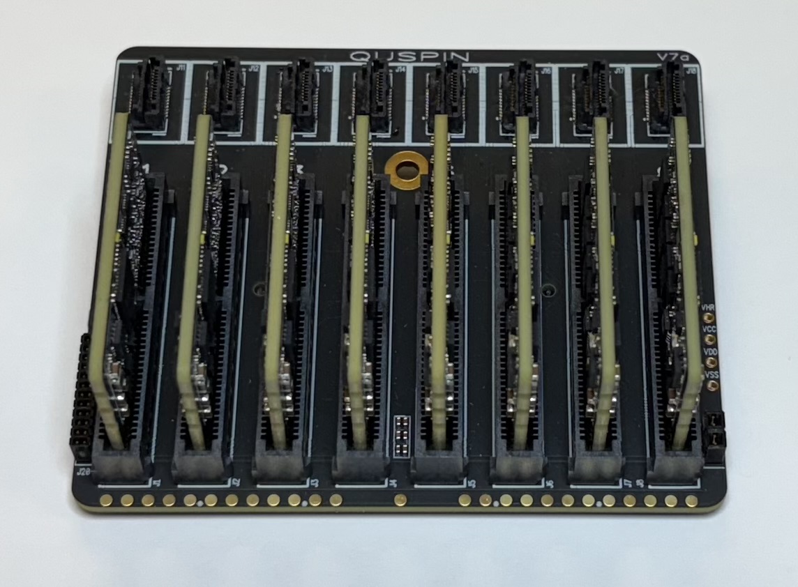
Complete 8-channel sensor module
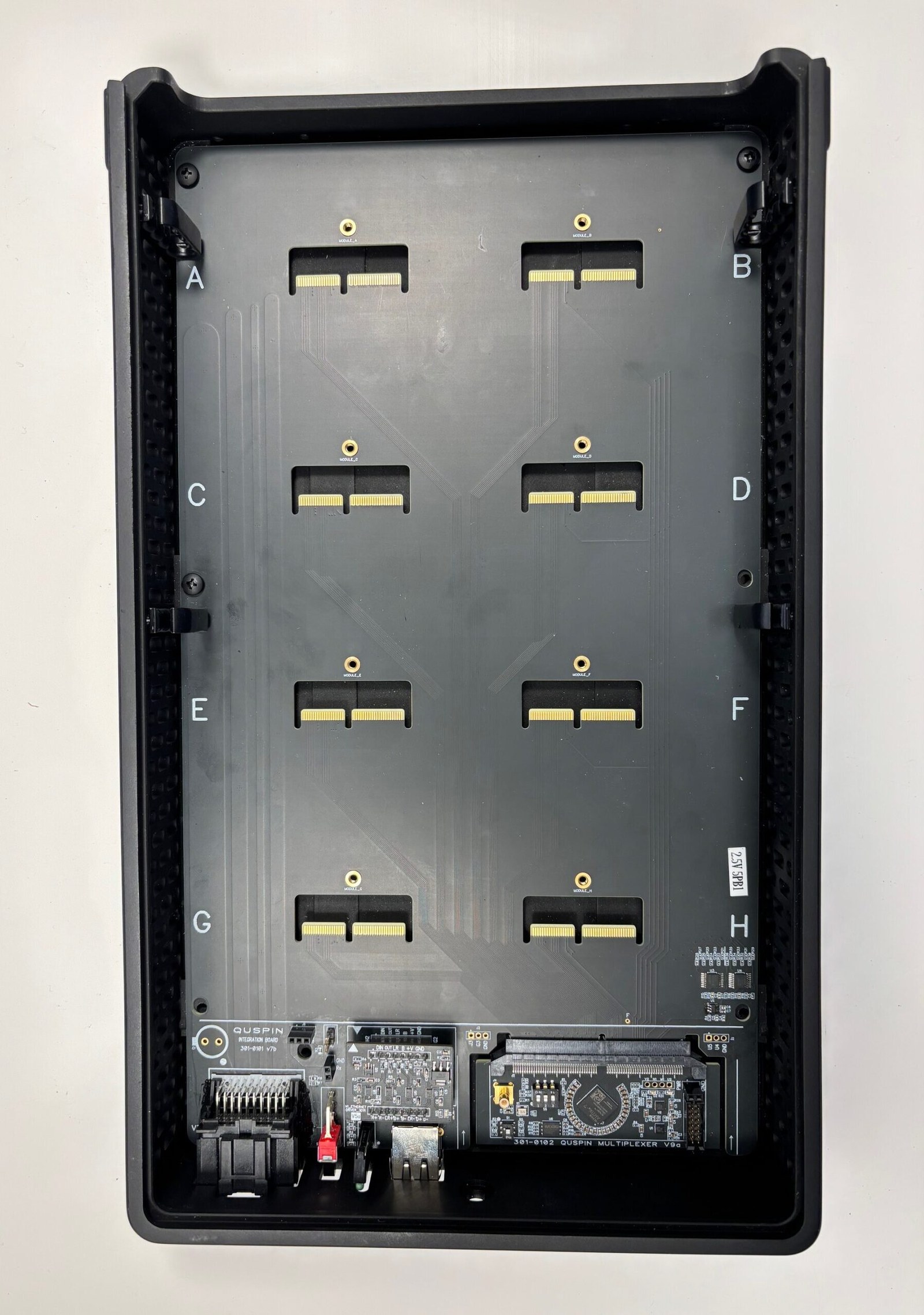
Holds 8 modules · 64 cardmags · 64 sensors
Each module contains 8 cardmags interfacing with 8 individual OPM sensors. Multiple modules combine in the backpack to create an array of up to 64 sensors; multiple backpacks extend this further.
Assembly steps
- 1 Prepare work area: set the backpack on a stable surface with plenty of room.
- 2 ESD precautions: ground yourself before unpacking modules and sensors.
- 3 Unpack components: keep modules in their ESD-safe bags until ready to connect. Set sensors down on a flat surface or secure holder.
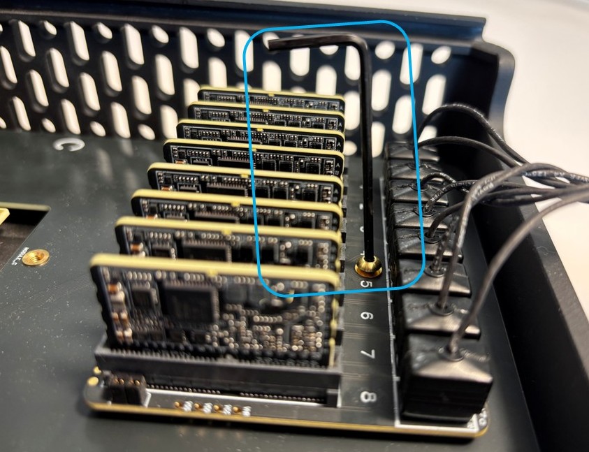
- 4 Install modules: one at a time, slide each into place on the backpack as shown in the video. Push on the base of the cardmag connectors—never on the cable connection at the front of the module.
- 5 Secure module: lock each module into place with the provided hex key and screw.
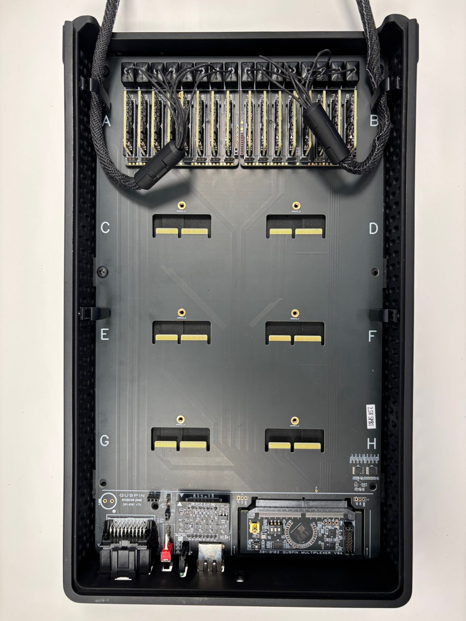
- 6 Cable management: route sensor cables into the cable routers for strain relief. Each router has 4 channels—push cables all the way down so the routers hold all 4 cables per side.
- 7 Optional — secure cables: zip-tie the cable routers on the inside walls to lock cables into their channels.
- 8 Assembly complete—continue below to run the sensors.
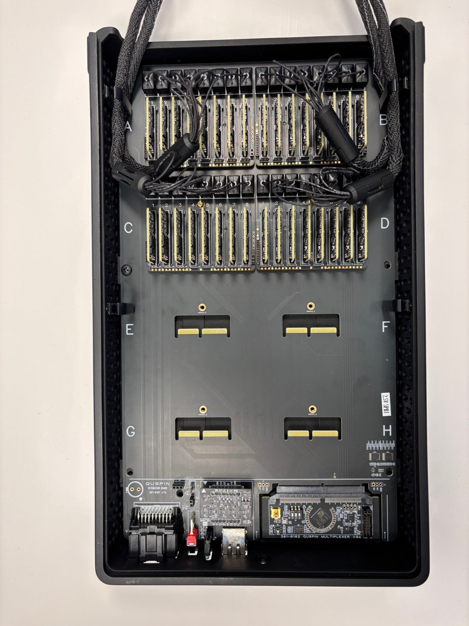
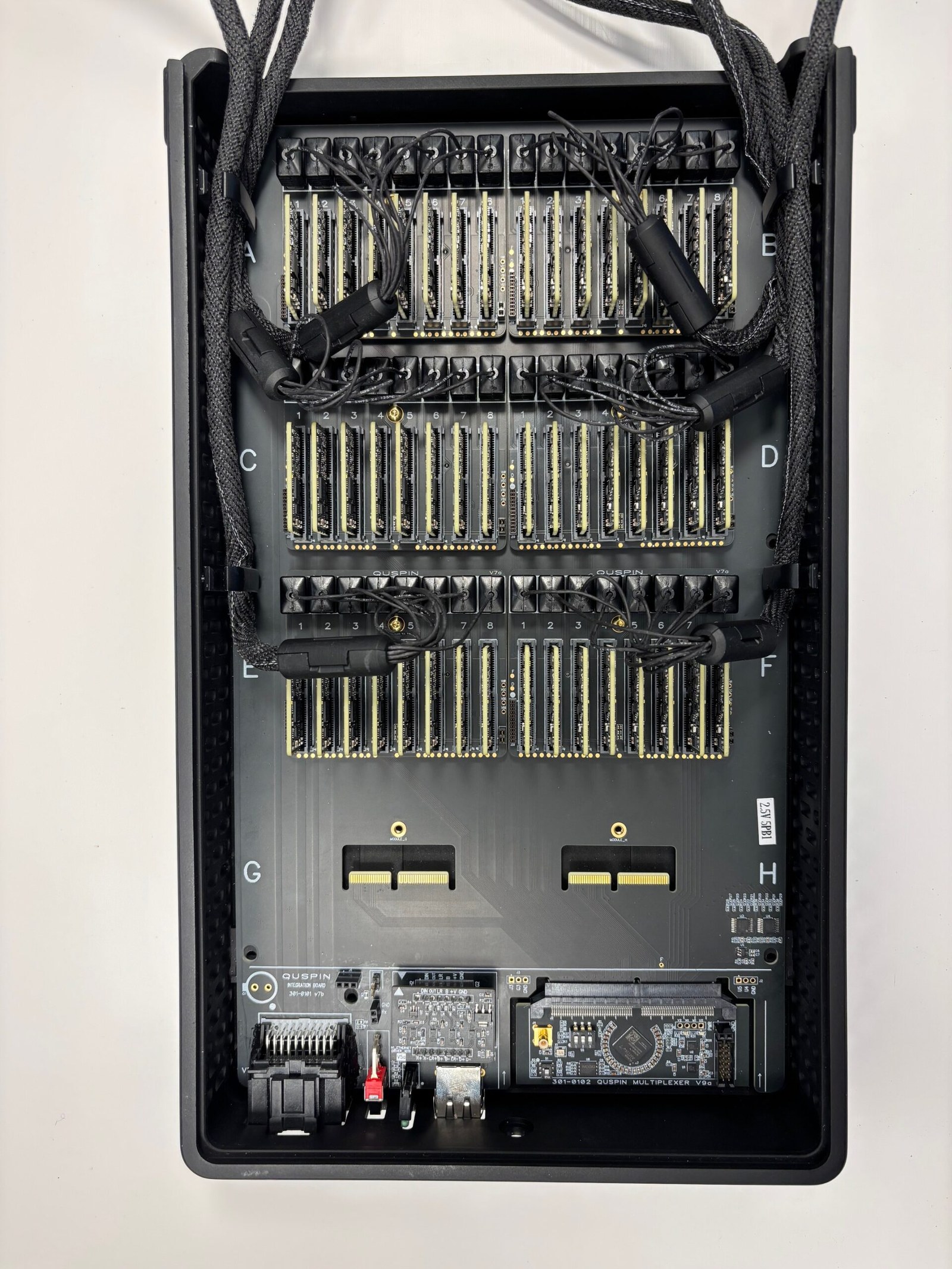
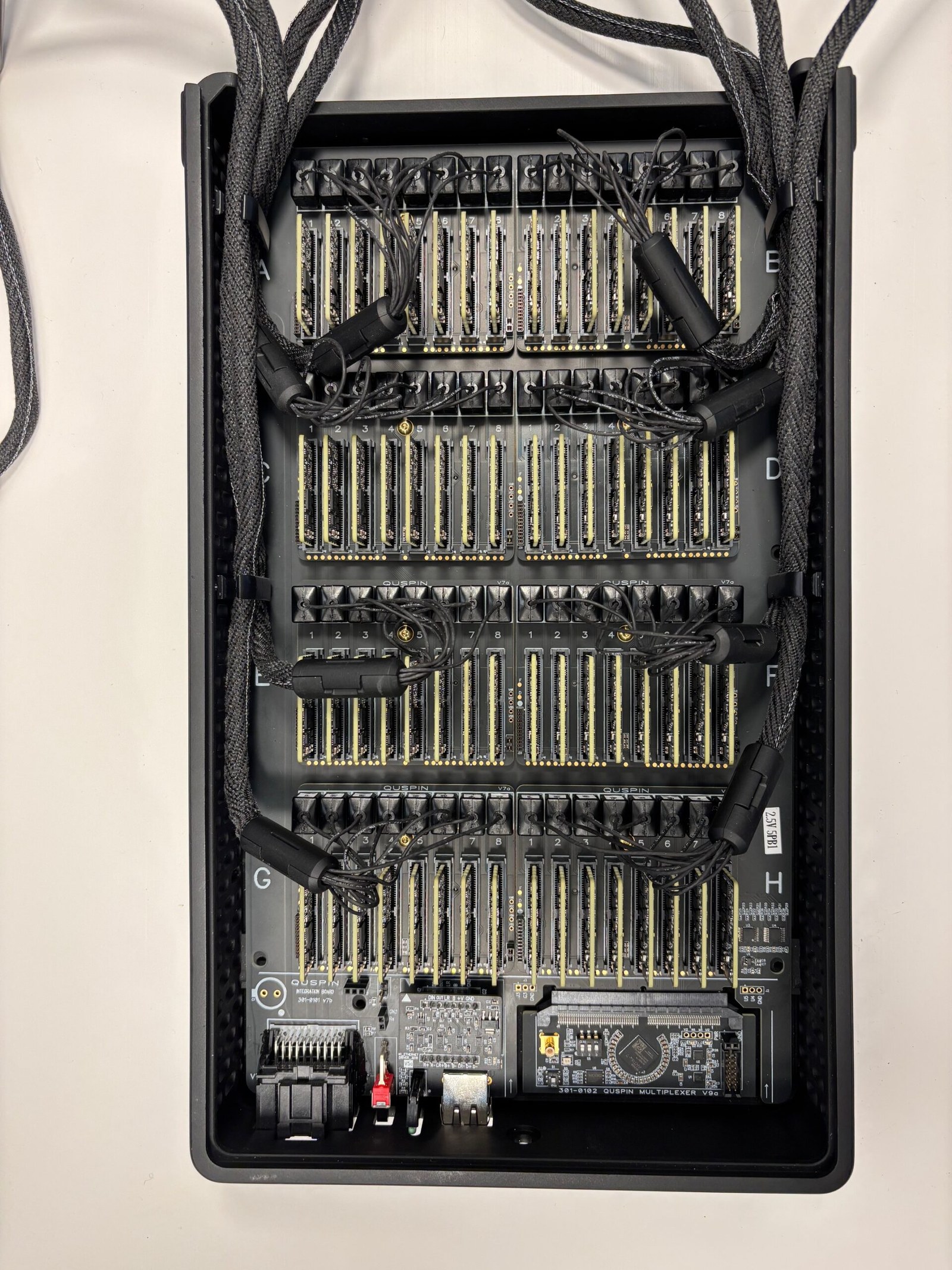
Safety reminder: always power off the system before making or changing sensor connections. Improper connection while powered can damage sensitive electronics.
Sensor operation
- 1 Power on the system.
- 2 Reconfigure Array (first run only): assigns correct channel numbers to the cardmags automatically.
- 3 Learn the N1 UI basics: setting the active state, deactivating sensors, reading status information (see video).
- 4 Auto Start: press Auto Start; wait for the “Laser Locked” LED to turn green and “Cell Temp Err” to stabilize.
- 5 Field Zero: V10 cardmags run continuous field zeroing by default after Auto Start; earlier cardmags need Field Zero On/Off commands to null the background field.
- 6 Ortho & Calibrate: once stable, press to measure and apply calibration values to the sensor data (see video).
- 7 Ready to record.
Let sensors stabilize 2–3 minutes after initialization before critical measurements. Monitor status LEDs to confirm all sensors are operating correctly.
V10 cardmags field-zero continuously by default; earlier versions require manual Field Zero commands. Verify your cardmag version before proceeding.
Coming soon: troubleshooting guide, saving data, noise floor viewing, firmware updates, HALO usage, and more N1 guides.
Developers
API
The N1 system exchanges data over TCP/IP. The DAQ acts as the server, allowing multiple client connections to read sensor, status, and system data, and to send commands.
| Port | Purpose |
|---|---|
| Port 8089 | Reading sensor data |
| Port 8090 | Reading sensor status data |
| Port 8091 | Reading system status data |
| Port 8092 | Sending command data to control the system |
Previous API versions: v1.6 · v1.3 · v1.2 Previous Python examples: Jul 2024 · Jan 2024
Reference
DAQ reference
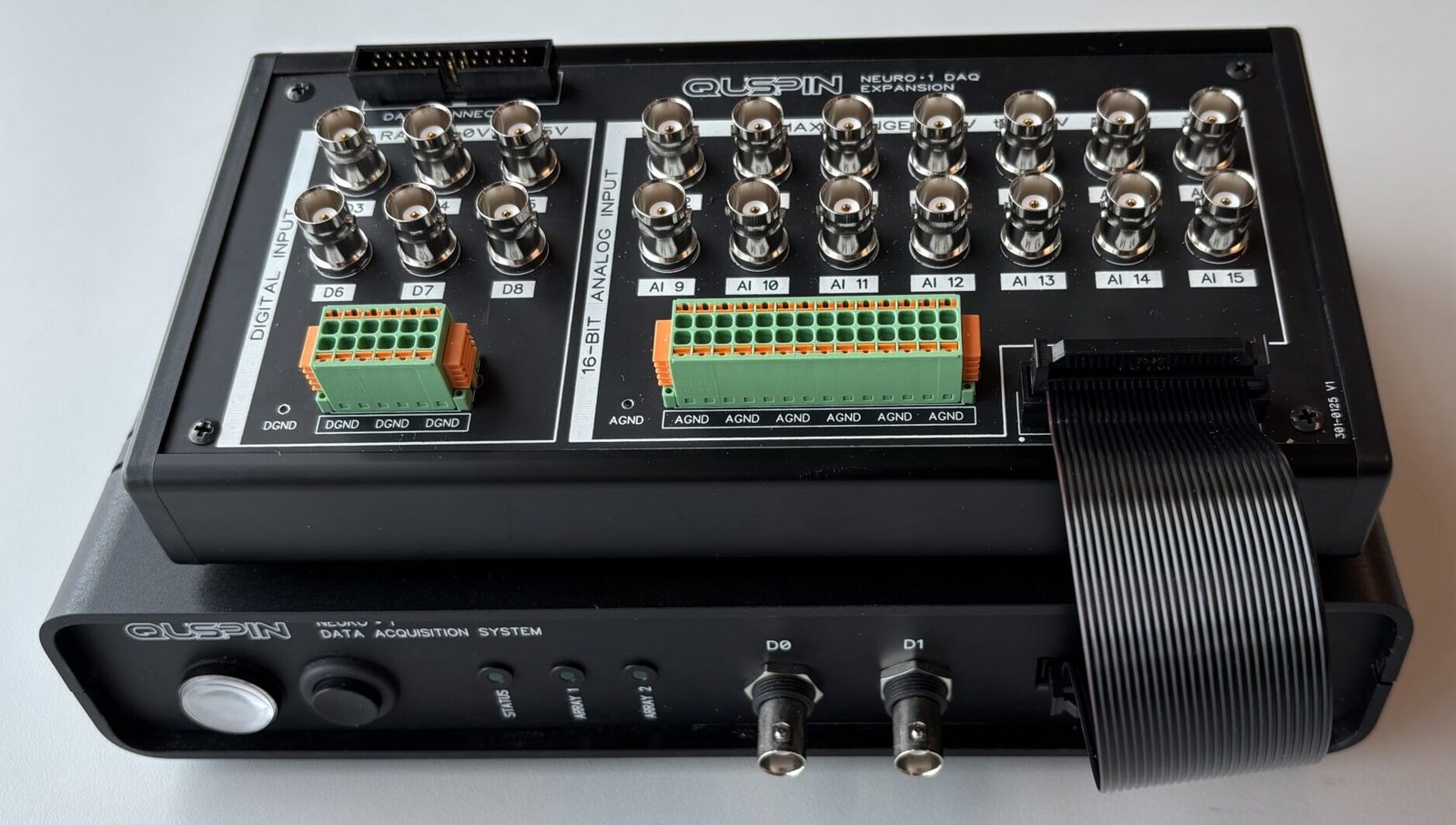
Front panel LED codes
| LED pattern | Status LED | Array 1 LED | Array 2 LED |
|---|---|---|---|
| Solid OFF | DAQ not running | Not connected | Not connected |
| Solid ON | DAQ running, connected to PC | Connected | Connected |
| Blink 1×, pause | DAQ running, not connected to PC | Clock error 1 | Clock error 1 |
| Blink 2×, pause | Unused | Clock error 2 | Clock error 2 |
| Blink 3×, pause | Unused | Clock error 3 | Clock error 3 |
DAQ hardware
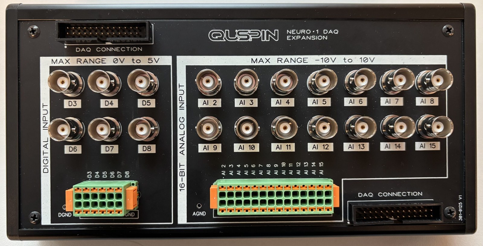
N1 UI saved data format
| Data | Saved label | Column(s) | DAQ / expansion pin |
|---|---|---|---|
| Time [seconds] | X_Value | 0 | — |
| X-axis data | X1 – X64 * | 1–64 | — |
| Y-axis data | Y1 – Y64 * | 65–128 | — |
| Z-axis data | Z1 – Z64 * | 129–192 | — |
| Digital inputs | D0 – D10 | 193–203 | DAQ: D0–D2 · Expansion: D3–D8 |
| Analog inputs | AI 0 – AI 15 | 204–219 | DAQ: AI 0–1 · Expansion: AI 2–15 |
| MUX counters | MUX_Counter1–2 | 220–221 | — |
| DAQ counter / data drops | DAQ_Counter1, Data_Drop1–2 | 222–224 | — |
| User comment | Comment | 225 | — |
* For Array 1 the X/Y/Z channels are labeled 1–64; for Array 2 (saved in a separate file) they are labeled 65–128.
HALO
High-resolution Array LOcalization
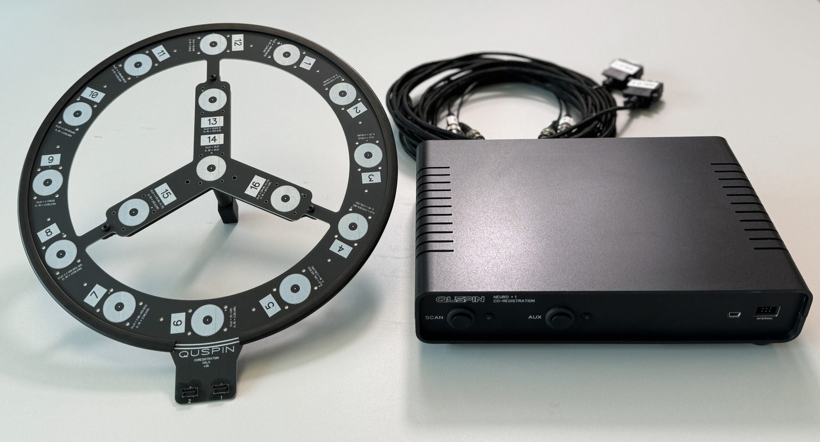
HALO is a turn-key platform for quickly and accurately determining the location, orientation, and calibration data for arrays of QuSpin OPMs — a streamlined, user-friendly approach to sensor localization, the first step in co-registration for advanced bio-magnetic sensing.
Co-Registration Setup Guide — start here
Co-Registration Workflow Tutorial