
1. Connecting ACB to QTFM
The ACB connects to QTFM Gen-2 with a custom flexible printed circuit (FPC) cable. The standard cable length is either two feet or six inches. To install the ACB, remove the cable from the standard comms board and connect the cable to the ACB as shown in the video GIF image below.
2. ACB connectors and power
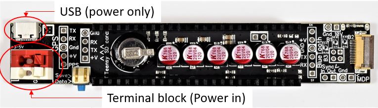
Power: The ACB must be powered with a power source that has an output voltage ranging from +3.5V to +5.5V (max) and a minimum current of 2 amps. Powering the ACB will power the entire system (ACB, QTFM ECU, QTFM sensor head, GPS, and Bluetooth module). There are two power input options for the ACB. (1) the red and white terminal blocks, or (2) the micro-USB connector. Note: The micro-USB connector is for power alone and does not support a USB data connection. When connecting the power supply using the red and white terminal blocks, please make sure the polarity of the power supply is correct. The positive voltage from the power supply should connect to the red terminal, and the ground/negative voltage should connect to the white terminal.
The two power inputs are ‘hot-swap’ compatible, and both can be powered on at the same time. This feature is particularly useful when using an external battery pack to power the ACB via the red-white terminal blocks. In this case, if you need to replace the battery pack quickly, the micro-USB cable can provide temporary holdover power while the battery is being swapped out.
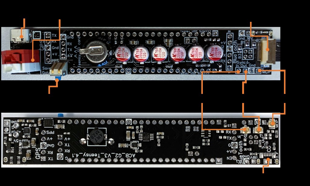
15-pin flex connector: This connector is used to connect the ACB to the QTFM electronics controller (ECU)
Sync-out (UMCC connector, output): 1 kHz, 3.3V square wave. The falling edge denotes the magnetic field measurement start time. Connecting sync-out from the master sensor to the sync-in of the slave sensor ensures the master and slave sensors are synchronized and make magnetic field measurements at the same instant.
Sync-in (UMCC connector, input): Accepts 1 kHz, 3.3V square wave to synchronize two or more QTFM Gen-2 sensors
Mag Data Pulse (MDP): +3.3V output pulse. MDP will stay low until the sensor has completed its AutoStart. The rising edge of MDP can be used as a jitter-free timestamp for the magnetometer data (1 pulse for each data sample that is transmitted)
Bluetooth
After powering on the ACB, you can communicate using a PC or smartphone over Bluetooth connection. The red light on the Bluetooth module will blink rapidly while waiting to be paired. To connect, go to settings on your device, select Bluetooth, then add a new device. The ACB should be discoverable as “QBT#” and the pairing password is “1234”. You should only need to pair with the ACB once. If you encounter any issues, try forgetting the device and pair again.
The Bluetooth module is programmed to default 115200 baud rate. Bluetooth can either transmit formatted data from the ACB (logger mode) or the raw data from QTFM (ECU mode), but not both simultaneously. A simple ASCII command (see below) can be sent to switch between the two modes.
When connecting to a PC, Bluetooth connection will show up as a serial com port. Once a connection to the com port is established, the red LED on the Bluetooth module will turn solid red. You can use the QTFM user interface to open the COM port and control the sensor, similar to when using the standard comms board (Bluetooth transmission should be set to ECU mode). Alternatively, you can use other terminal interfaces, such as Tera Term or PuTTY to communicate with the device in logger mode or in ECU mode. For iPhones, we recommend the Lightblue app, while for Android smartphones, the Serial Bluetooth Terminal works well.
Viewing data from the ACB in logger mode is helpful to verify that no pre-arm errors have been detected and that the logger is ready to save data.
When an ASCII command is sent to Bluetooth, it is read by both the sensor and the ACB independent of its transmission mode (logger/ECU). Below is a list of the ASCII commands for the ACB.
| Decimal | ASCII | Command |
|---|---|---|
| 102 | f | Start saving data to SD card |
| 103 | g | Stop saving data to SD card |
| 104 | h | Switch BT to transmit in 'ECU' mode |
| 65 | A | Switch BT to transmit in 'logger' mode |
Once logging has been initiated, it is recommended that you do not send commands to the sensor via Bluetooth except for the four commands above. You may configure the sensor using Bluetooth, but it should be done before data saving is active.
Configuring the logger
Once the ACB starts, it will load settings from a file named !quspin!.ini, located
on the SD card. To configure the logger, edit this file on the SD card and save the changes.
You can use Notepad on Windows for editing. Ensure the file is saved with the name
!quspin!.ini. The default (suggested) configuration for !quspin!.ini
is provided below.
;Start
; configure QuSpin logger operation
[config]
;
USE_GPS = true
; PA1616D and PA6H set GPS_TYPE=1
; NEO-M8N set GPS_TYPE=2
; NEO-M9N set GPS_TYPE=3
; PA1616S set GPS_TYPE=4
GPS_TYPE=1
PPS_TIMESTAMP = true
MAGDATA_PULSE_TIMESTAMP = true
MAX_FILE_SIZE_BYTES = 671088630
LOG_AT_STARTUP = false
MAG_DATA_REPEATER = false
RADIO_RATE = 57600
DEMO_MODE = false
LOG_FILE_BINARY = false
GPS_RATE = 115200
FILE_NAME_PREFIX = TFM
SLAVE_PRESENT = false
;End
Pre-arm checks
When the ACB is powered up the teensy will begin its pre-arm checks. The logger will not initiate logging until it has successfully passed all of its pre-arm checks. If any part of the pre-arm check fails, the logger will restart the pre-arm check process until the pre-arm check is successful. The pre-arm checks are outlined below.
- 1
The SD card is in the teensy SD card slot, and a
!quspin!.inifile is on it. - 2 The logger will confirm that it is receiving data from the QTFM ECU. Note: This check only determines if sensor data is being received. It does not determine if the sensor is locked or if the sensitivity indicator is strong. To ensure the sensor is locked and outputting good data, check if the LED on the ECU is solid blue. You can also stream raw sensor data over Bluetooth to confirm by changing the ACB transmit mode to ‘ECU’.
- 3
This check only occurs if the
USE_GPS = truein the!quspin!.inifile on the SD card. This check determines if communication between the GPS and logger has been established. It also determines that the GPS unit that is attached matches theGPS_TYPEin the!quspin!.inifile. Finally, this check will not pass until the GPS unit has successfully found a fix. Depending on the location, a GPS fix can take up to 20 minutes even when you are outdoors. Attaching an external antenna can speed up this process. - 4
This check only occurs if the
PPS_TIMESTAMP = truein the!quspin!.inifile on the SD card. This check determines that the logger is receiving a PPS signal from the GPS unit. - 5
This check only occurs if the
MAGDATA_PULSE_TIMESTAMP = truein the!quspin!.inifile on the SD card. This check determines that the logger is receiving a Magdata pulse from the sensor. The sensor will only begin outputting a mag data pulse once it has achieved a lock.
Once the logger has passed its pre-arm checks successfully, it will move into a ready state,
and logging is ready to be initiated. If LOG_AT_STARTUP = false in .ini file, the
LED on the ACB will begin to blink blue. At this point, you can initiate logging through
Bluetooth command ‘f’, or by pushing the blue button on the ACB. Make sure you are
in ‘logger’ mode to initiate logging. The LED on the ACB will go to solid blue when
it has begun logging. If LOG_AT_STARTUP = true in .ini file the logging will begin
as soon as the pre-arm checks pass successfully.
If the pre-arm checks are not passing, connect to the Bluetooth to read out any errors (send command ‘A’ for ‘logger’ mode). The logger will continuously send updates via Bluetooth of the pre-arm check status.
Data conversion
The data log files saved to the SD card are in .txt format. Files will contain a verbatim dump of everything the QTFM and GPS transmits. Responses to commands, status messages, and star codes are timestamped and interleaved between mag data packets. If a GPS module is connected, enabled in the config file, and operational, then time and position data is also logged. The logging file format is chosen for the efficiency and reliability of logging but is not very convenient for viewing or analysis. For this reason, some post-processing of the log files is necessary before viewing the mag data, and a utility is provided for this purpose.
To view the log file(s)
- Terminate logging by momentarily pressing the blue switch before removing the card
- Remove the SD card and mount it on a PC
-
Download the QLog_Processor application, then drag a
.txtlog file ontoQLog_Processor.exe, or onto a desktop shortcut. -
Three comma-delimited
.csvfiles are produced, plus a_summary.txtlisting the run statistics and every status line from the log: a flat-file format in_flat.CSV, a GPS/UTC consolidated table in_dedup.CSV, and an analysis-ready_interpolated.CSVresampled to a uniform timebase.
Which timestamp to use in the output
Whichever CSV you work from, take your time base from the
QTFM’s standard millisecond timestamp (the > field) —
it comes from the sensor’s own clock and is jitter-free.
The microsecond timestamp added by the logger, and the uniform timebase the
_interpolated.csv is resampled onto, are derived from the logger’s clock.
They are useful for aligning data to GPS time and for spotting dropped samples, but
should not be treated as the measurement time base. If your results depend
on precise sample timing, work from the sensor’s millisecond timestamp. See
Serial Communication and Data
Format.
Coming from QLogConverter?
QLog_Processor is the new name for this tool. It replaces the two older converters, which is
why the name changed — and the output set changed with it: you now get
_flat / _dedup / _interpolated CSVs rather than the
old standard / flatCSV / geospatial folders. The old Google Doc manual is retired; use this
page and the
QLogMonitorConsole
page instead.
SHA-256 · QLog_Processor.exe 0f8c059d4de6b5ebe79f3e1c70eddf062ac3f9ff1f4006ee6701bf0e5babb4e5
SHA-256 · Qlog_ConverterV5.py b8856f9cebd4f5b20ac9e775573d002d86b6658abe6944971ec9a9a5988c5381
The Python file is the same tool as a single source file, for anyone who wants to read it,
check it, or run it on a machine that is not Windows. Run it as
py Qlog_ConverterV5.py yourlog.txt, or pass several logs at once. The executable
is this file packaged with PyInstaller.
Updated 9 October 2026 — what changed
The UTC time column now carries milliseconds, under the header
TimeUTC(HH:MM:SS.sss); earlier builds printed whole seconds. The data counter and
the two sensitivity indicators are no longer interpolated between measurements. A log
containing a truncated line no longer stops the conversion. A line whose timestamp does not
belong with the lines around it is discarded and reported instead of being used, and rows
stamped exactly zero at the start of a session are dropped; the summary file lists every row
removed this way. The converter now refuses to build a time axis it cannot support, and says
so. All of these were reported by users — if you are running a build dated before this
one, replace it.
Excel silently truncates large logs A worksheet holds at most 1,048,576 rows. A log of approximately 54.2 MB is about 4,169,230 records, so Excel discards roughly three million rows — without a clear warning that your data is incomplete. For files this size use QLog_Processor or another tool built for them, not a spreadsheet.
QLogMonitorConsole App New
QLogMonitorConsole app is available for download here
Its conversion is not the same as QLog_Processor’s.
QLogMonitorConsole runs its own built-in conversion while it transfers a file, producing a
different set of output files than the _flat / _dedup /
_interpolated CSVs QLog_Processor makes. If you need the QLog_Processor outputs,
run QLog_Processor on the raw .txt; for what QLogMonitorConsole itself produces,
see the QLogMonitorConsole
page.
The QLogMonitorConsole app is a multifunctional tool designed to simplify your experience with
the logger. Download files from the SD card to your PC without removing it, and they’ll
be automatically formatted just like QLog_Processor does. Change the logger settings
(without manually editing the !quspin!.ini fille), receive logger status updates,
start and stop logging, and update the logger’s firmware, all within the app. To begin,
connect a USB cable from your PC to the logger port and launch the QLogMonitorConsole app.
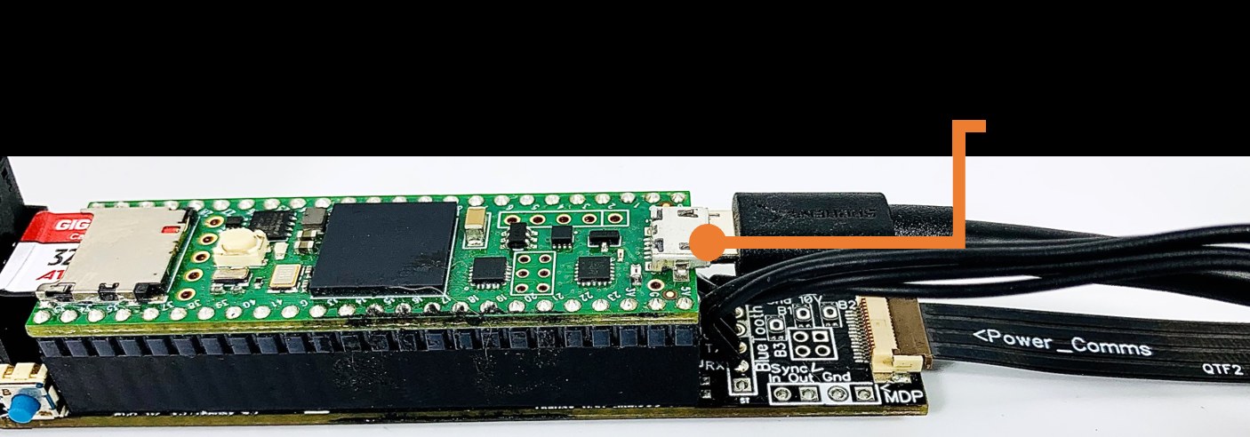
If your logger’s firmware is outdated, the QLogMonitorConsole app might not recognize it. In that case, you’ll need to manually update the logger firmware once before using the app. You can download the latest firmware here. Just download the folder to your PC, connect to the logger port, and run LoadLogger.bat to update the firmware. From then on, all future logger firmware updates can be easily handled within the QLogMonitorConsole app.
If the application isn’t functioning properly, please check the
!quspin!.ini file on the SD card. Insert the SD card into your PC to access and
modify the file as needed. Ensure that it matches the configuration below:
;Start
; configure QuSpin logger operation
[config]
;
USE_GPS = true
; PA1616D and PA6H set GPS_TYPE=1
; NEO-M8N set GPS_TYPE=2
; NEO-M9N set GPS_TYPE=3
; PA1616S set GPS_TYPE=4
GPS_TYPE=1
PPS_TIMESTAMP = true
MAGDATA_PULSE_TIMESTAMP = true
MAX_FILE_SIZE_BYTES = 671088630
LOG_AT_STARTUP = false
MAG_DATA_REPEATER = false
RADIO_RATE = 57600
DEMO_MODE = false
LOG_FILE_BINARY = false
GPS_RATE = 115200
FILE_NAME_PREFIX = TFM
SLAVE_PRESENT = false
;End
A more detailed QLogMonitorConsole App manual is available here