
♦ Quick Start — Part A: Covers using QTFM G2 with a standard comms board plugged into a Windows PC.
*Standard comms board is included with every sensor.
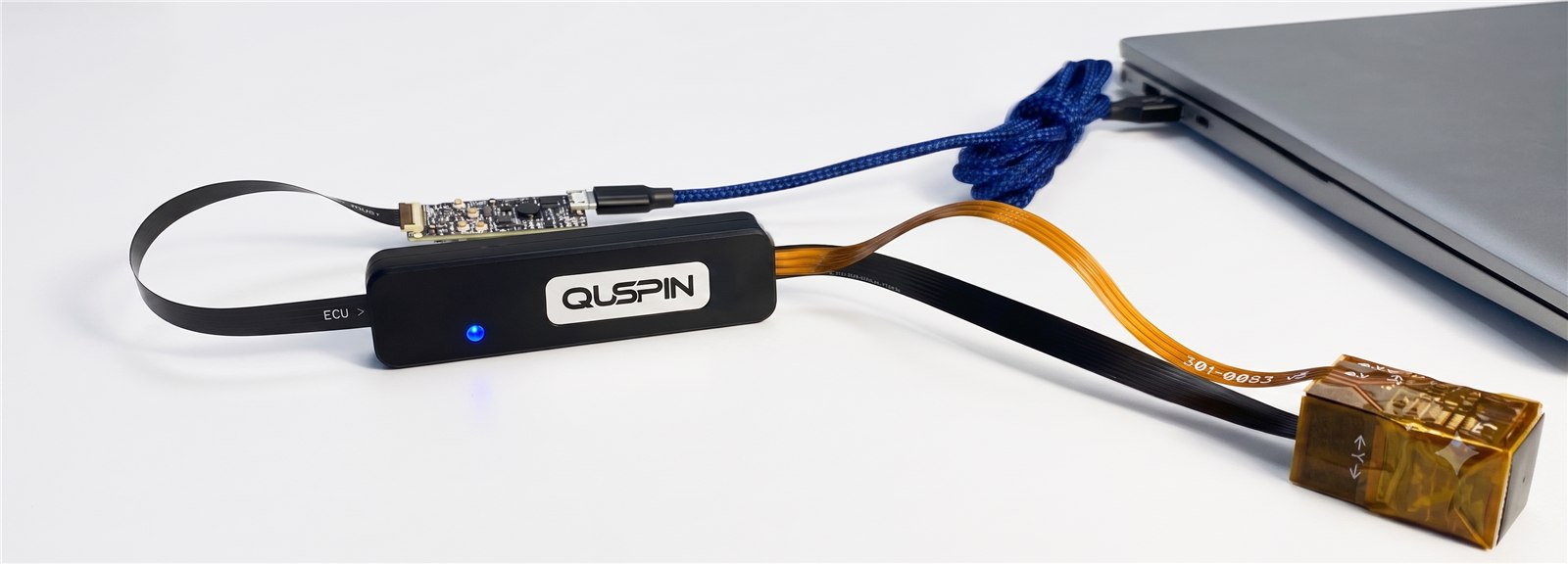
Scope
This guide covers using a QTFM Gen‑2 with the Standard Comms Board plugged into a Windows PC. A Standard Comms Board is included with every sensor.
If you are using the Advanced Comms Board (ACB 2.0) — for SD logging, GPS, or Bluetooth — see the ACB 2.0 Quick Start instead.
Components
| Component | What it does |
|---|---|
| Sensor head with triax coils | Integrated optics package with the laser and rubidium vapour cell that senses the magnetic field. |
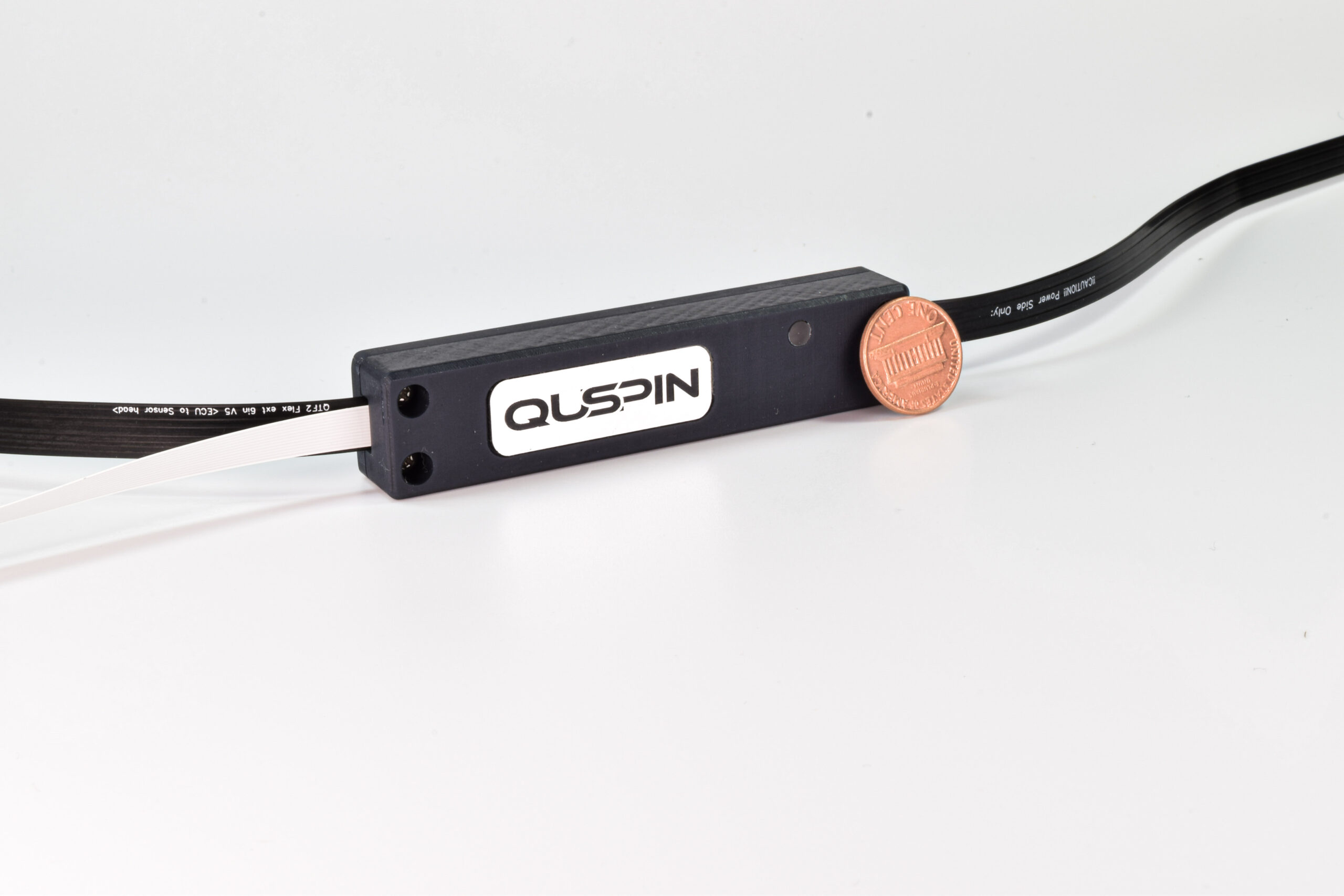
| Electronics controller unit (ECU) | Control electronics for the sensor head. |
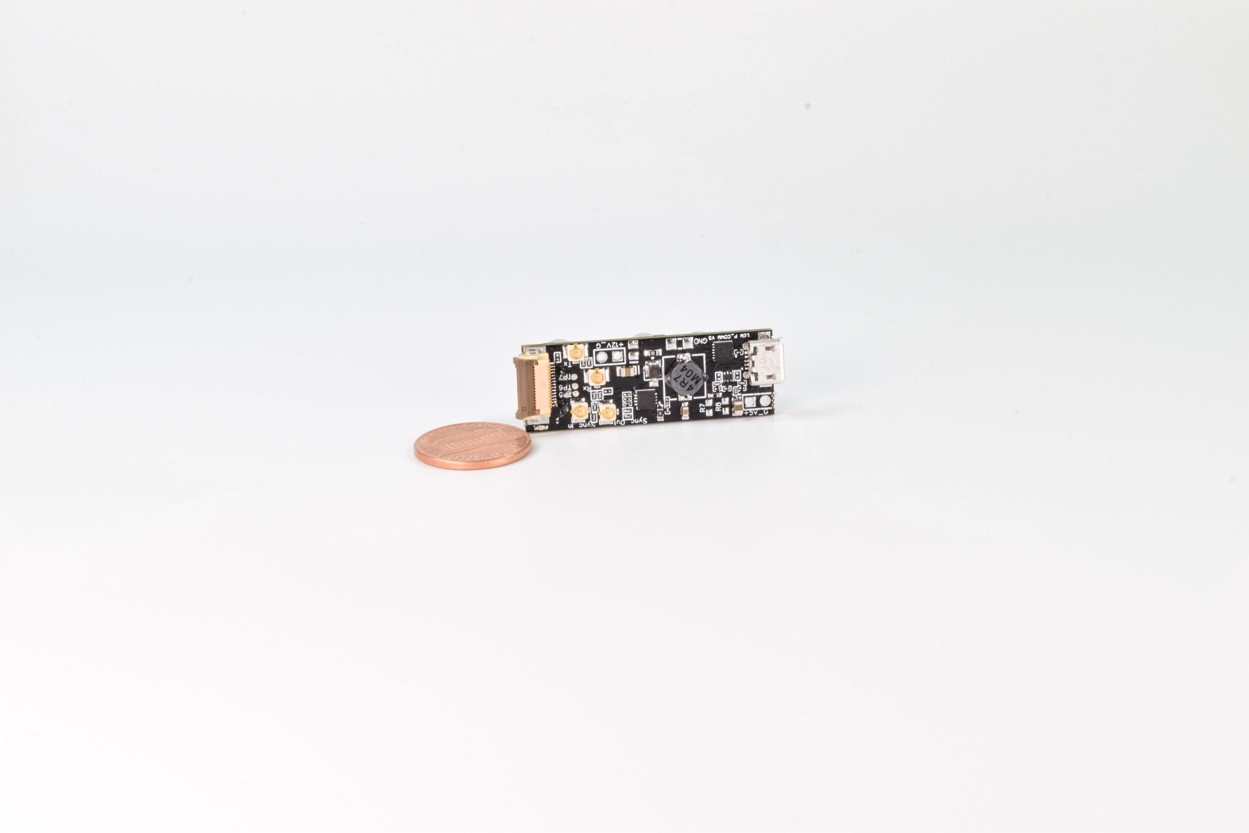
| Standard Comms Board | Power regulation, USB–UART communications bridge, and access to timing and raw digital signals. |
| A Windows PC | Runs the QTFM Gen‑2 user interface. |

Hardware setup
The QTFM G2 sensor head is connected to its electronics controller (ECU). The ECU is connected to a standard comms board, and finally, the standard comms board connects to the PC with a USB cable.
Note Keep the sensor head away from ferrous objects and interference-producing electronic devices such as laptops and power supplies when operating (with a longer USB cable). Ideally, the sensor head should be placed on a non-magnetic surface and a few feet away from electronic devices such as laptops.
Install the user interface (Windows)
| Filename | UI framework | Release Date | Notes |
|---|---|---|---|
| QTFM2_UI_V4_10_5_Setup.exe Latest | Python | September 29, 2026 | Bug fixes for the settings file |
| QTFM2_UI_V4_10_4_Setup.exe | Python | June 23, 2026 | Auto scan UART baud rate button added to the connection window, bug fixes, layout edits |
| QTFM2_UI_V4_10_Setup.exe | Python | May 21, 2026 | Bug fix for Amplitude Spectral Density plot |
| QTFM2_UI_V4_09_Setup.exe | Python | April 16, 2026 | Updated layout and bug fixes |
| QTFM2_UI_V1.36_Setup.exe | LabVIEW (legacy) | March 31, 2025 | |
| QTFM2_UI_v1.29_Installer.exe | LabVIEW (legacy) | February 2, 2024 | Initial release |
LabVIEW runtime prerequisites
The LabVIEW-based (legacy) UI releases above also require this runtime installer.
Identify the COM port
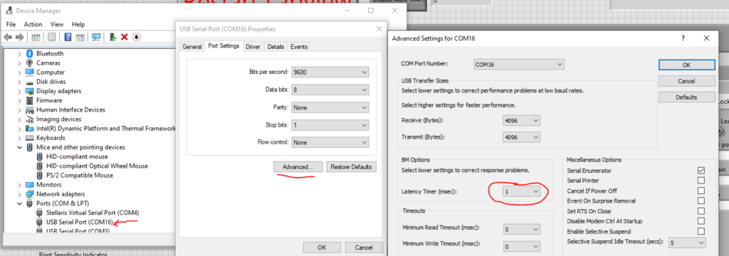
Open device manager on your Windows PC, and expand the list under the “Ports” menu. The device manager can be opened, for example, by searching for “device manager” in the Windows search bar. When the USB cable connected to the standard comms board is plugged into the PC, a new COM port will appear in the ports list. The newly added port corresponds to QTFM.
Note For the fastest data transfer speed to the PC, right-click on the COM port corresponding to the sensor in the device manager and select, Properties > Port Settings > Advanced and set Latency Timer (msec) to 1 instead of 16 which is the default.
Using the QTFM Gen-2 software
Videos load from YouTube only when you click one. Set playback resolution to 1080 for the clearest view of the interface.
Part-1: Com port selection, starting the sensor, and visualizing data [2m:18s]
Part-2: Front panel user interface controls (Chart Length, Data Rate, Filters) [1m:32s]
Part-3: Terminal tab to visualize raw data and select Print Items [00m:48s]
Part-4: Hybrid Scalar-Vector Mode [01m:18s]
Part-5: File Save [01m:30s]
Notes
Part-1
- To release the com port, close the user interface or press the “End” key on your PC.
Part-2
- Data rate and filter settings are permanent variables. Selected values will be retained after rebooting or power cycle.
- A data rate of 0.004 s indicates that the sensor is outputting one sample every 0.004 s, i.e. 250 Hz.
- At slow data rates, activating a 10 Hz or lower frequency low-pass filter is recommended to remove aliasing artifacts from 50/60 Hz power line noise.
Part-3
- Raw data can also be seen with any terminal program, for example, TeraTerm at 115,200 baud rate (default).
- Print item selections are stored in permanent variables and not erased after power cycle or reboot. More details on print items can be found in the detailed user guide.
Part-4
- Requires vector coil attachment.
Part-5
- The file formatting option shown here is only for files saved on the PC with the standard comms board. Files saved on the SD card of the advanced comms board are processed separately. If you have an earlier advanced comms board, see QLogMonitorConsole and the Advanced Comms Board quick start; both cover the older tooling. For current ACB hardware, contact info@quspin.com.